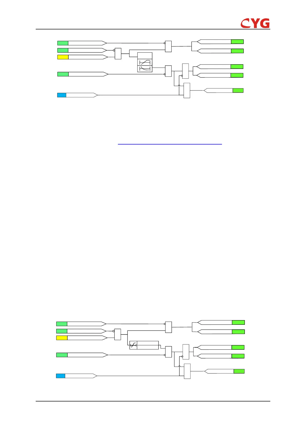
Figure 3.2-3 Functional module diagram for 51P
Once initiation logic is fulfilled and no blocking signal is activated, the 51P_Str signal is set. The
51P_Str_A, 51P_Str_B and 51P_Str_C outputs are used to indicate which phases are started.
The timer model is determined by IDMT curves for over quantity protection
The operation is activated after the operation timer has reached the calculated value. However,
51P_Min_Op_T defines the minimum desired operate time for IDMT. If a drop-off situation
happens, that is, a fault suddenly disappears before the operate delay is exceeded, the operation
will reset after the set value 51P_Reset_T is exceeded.
NOTICE!
The 51P_Min_Op_T setting should be used with great care because the operation time
is according to the IDMT curve, but always at least the value of the 51P_Min_Op_T
setting.
The binary input 51P_Blk can be used to block the function. The activation of the 51P_Blk input
deactivates all outputs and resets internal timers. The binary input 51P_Blk_Str can be used to
block the start signals. The binary input 51P_Blk_Op can be used to block the operation signals.
3.2.2.2 50P
The overcurrent protection in this relay provides instantaneous phase overcurrent protection. The
overcurrent module, phase selection module, time characteristic settings apply to all three phases
and are independent from each other. Configuring the relevant settings can enable or disable the
corresponding protection.
The principle is same as the 51P except 50P time delay is instantaneous.