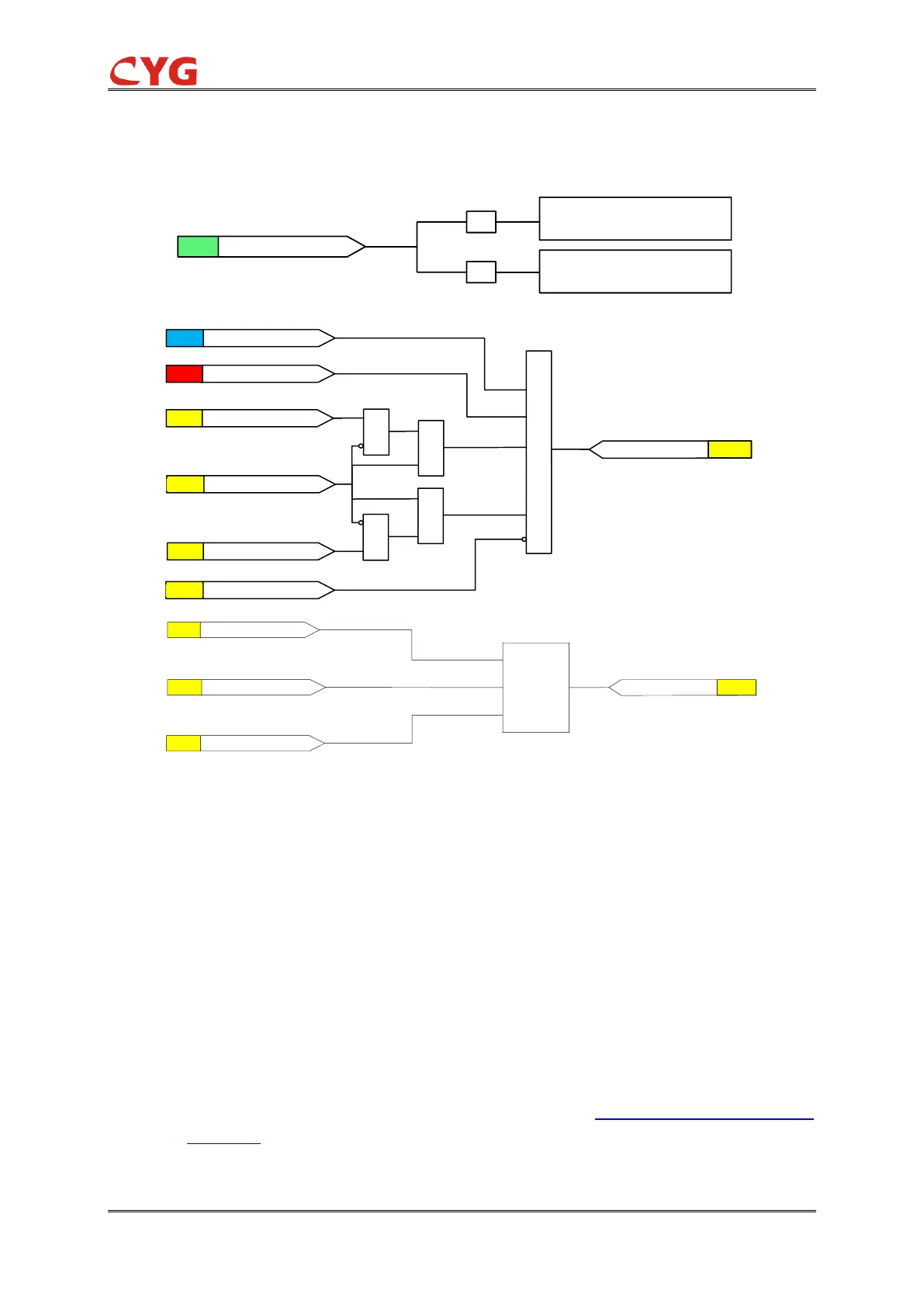
Figure 3.3-5 The initiation logic diagram
The measured phase currents are compared phase wise to the set 67P_Cur_Str. If the measured
value exceeds the set 67P_Cur_Str the level detector reports the exceeding of the value to the
phase selection logic. If the 67P_Ena_Mult input is active, the 67P_Cur_Str setting is multiplied by
the 67P_Mult_Cur_Str setting.
The start value multiplication is normally used in case that the inrush situation happens.
NOTICE!
Do not set the multiplier setting 67P_Mult_Cur_Str higher than necessary. If the value is
too high, the function may not operate at all during an inrush followed by a fault, no
matter how severe the fault is.
The start value multiplication is normally done when the inrush detection function
(OCR_INR) is connected to the Ena_Mult input by Three phase inrush function
OCR_INR.
If the fault criteria are fulfilled in the current level and the directional calculation, the phase