20
31
32
33
34
35
1
2
3
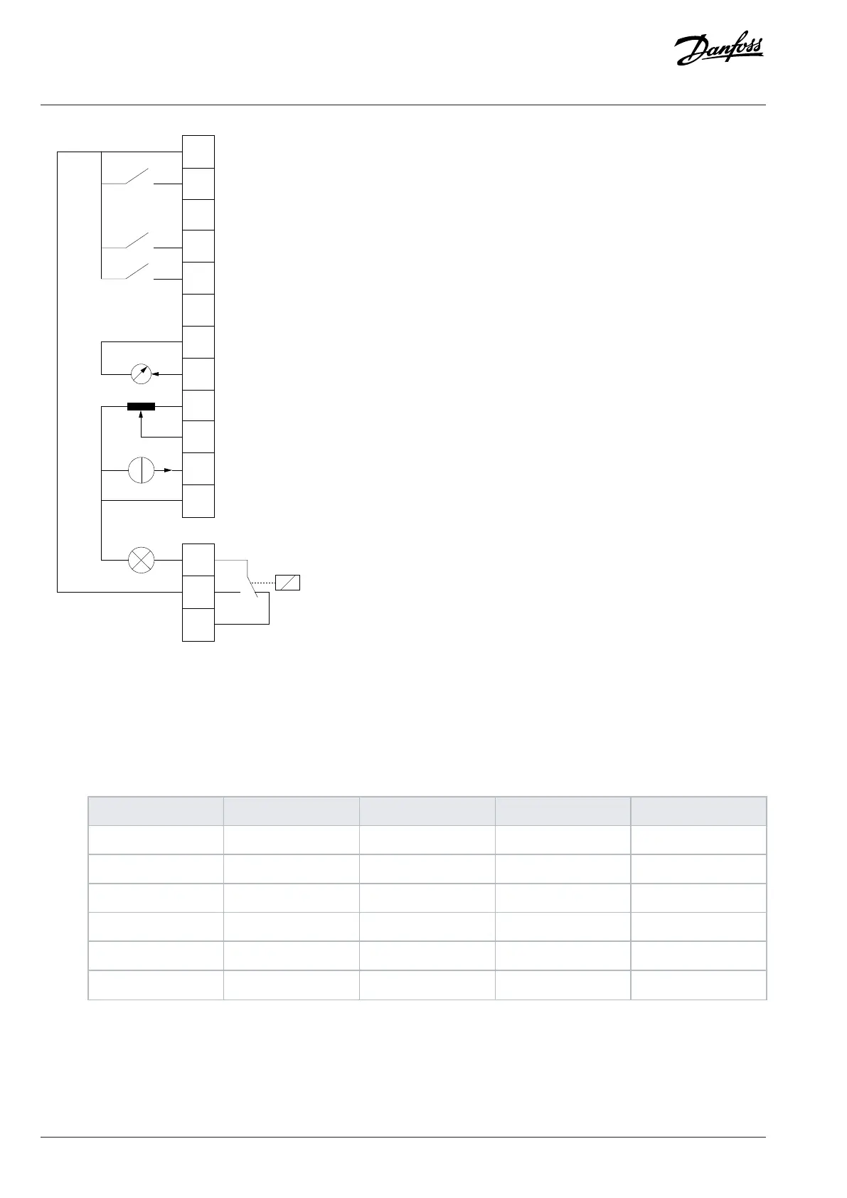
RELAY
Fault
GND
AI2
AI1
10V
AO1
GND
DI4
Output Frequency
Process Reference 1
Process Feedback
Figure 38: Default Connections for Process Control
1. Set P 5.4.1 Application Selection to [21] Process Control Mode.
When [21] Process Control Mode is selected, the following parameters are automatically set to the values shown in the table.
Table 16: Process Control Mode Default Settings
Category Parameter index Parameter name Default setting Parameter number
Operation Mode 5.4.2 Operation Mode [3] Process Close Loop 100
DI 1 - T13 9.4.1.2 T13 Digital Input [8] Start 510
DI 2 - T14 9.4.1.3 T14 Digital Input [0] No operation 511
DI/O - T15 9.4.1.4 T15 Digital Input [1] Reset 512
DI 3 - T17 9.4.1.5 T17 Digital Input [14] Jog 513
DI 4 - T18 9.4.1.6 T18 Digital Input [0] No Operation 515
58 | Danfoss A/S © 2024.03 AB413939445838en-000301 / 130R1254
Application Guide | iC2-Micro Frequency Converters