Application Guide | iC2-Micro Frequency Converters
Local bus ref.
No function
Analog ref.
Pulse ref.
Analog ref.
Pulse ref.
Local bus ref.
No function
Local bus ref.
Pulse ref.
No function
Analog ref.
Input command:
Catch up/ slow down
Catchup Slowdown
value
Freeze ref.
Speed up/ speed down
ref.
Remote
Ref. in %
-max ref./
Scale to
Nm
Scale to
process
unit
Relative
X+X*Y
/100
max ref.
min ref.
D1
P 9.4.2.1x(15)
Preset '1'
External '0'
Process
Torque
Speed open loop
(1)
Ref.resource 1
P 5.5.3.7
Ref. resource 2
P 5.5.3.8
P 5.1.16
P 5.1.17
P 5.5.3.13 Freeze Up/
Down Step Delta
P 9.4.2.1x(21)/P 9.4.2.1x(22)
P 9.4.2.1x(28)/P 9.4.2.1x(29)
P 9.4.2.1x(19)/P 9.4.2.1x(20)
P 5.5.3.5
Reference
Function
(0)
Freeze ref.
&
increase/
decrease
ref.
Catch up/
slow
down
P 5.5.3.10
Control Panel
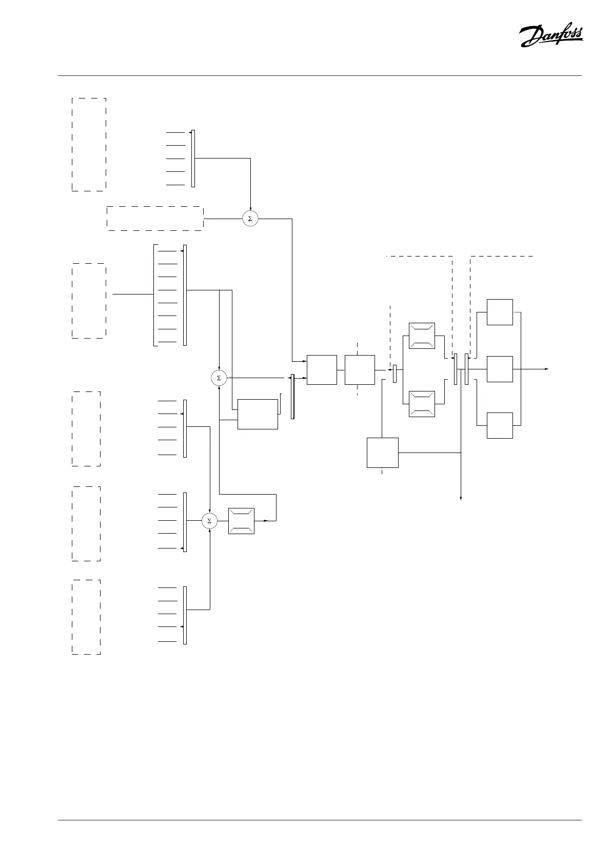
Figure 43: Remote Reference
The remote reference is calculated once in every scan interval and initially consists of 2 types of reference inputs:
l X (the external reference): A sum (see P 5.5.3.5 T34 Low Current) of up to 4 externally selected references, comprising any
combination (determined by the setting of P 5.5.3.7 Reference 1 Source, P 5.5.3.8 Reference 2 Source, and P 5.5.3.9 Reference 3 Source)
of a fixed preset reference (P 5.5.3.10 Preset Reference), variable analog references, variable digital pulse references, and various
fieldbus references in any unit the drive is monitoring ([Hz], [RPM], [Nm], and so on).
l Y (the relative reference): A sum of 1 fixed preset reference (P 5.5.3.11 Preset Relative Reference) and 1 variable analog reference (P
5.5.3.12 Relative Scaling Reference Resource) in [%].
Danfoss A/S © 2024.03 AB413939445838en-000301 / 130R1254 | 67