Application Guide | iC2-Micro Frequency Converters
10
V
V
20
1
10
-20
e30bk092.10
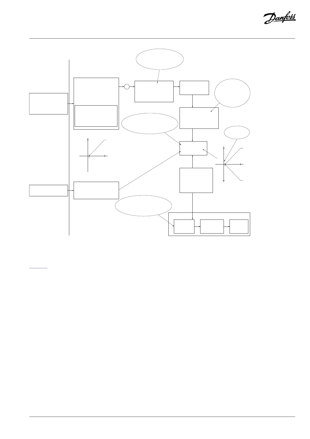
Low voltage 1 V
High voltage 10 V
100.0% (20 Hz)
0.0% (0 Hz)
Range:
Reference is scaled
according to min
max reference giving a
speed.!!!
Scale to
speed
+20 Hz
-20 Hz
Range:
Speed
setpoint
Motor
control
Range:
-8 Hz
+8 Hz
Motor
Low No reversing
High Reversing
Limits Speed Setpoint
according to min max speed.!!!
Motor PID
Reference Range: Min - Max
Minimum Reference: 0 Hz (0,0%)
Maximum Reference: 20 Hz (100,0%)
Motor speed direction:Both directions
Motor speed Low limit: 0 Hz
Motor speed high limit: 8 Hz
Figure 49: Clamping of Reference Input with Limits inside Minimum to Maximum
Case 2: Positive reference with dead band, digital input to trigger reverse, part II
Figure 50 shows how reference input with limits outside -maximum to +maximum limits clamps to the input low and high limits before
adding to external reference, and how the external reference is clamped to -maximum to +maximum by the reference algorithm.
Danfoss A/S © 2024.03 AB413939445838en-000301 / 130R1254 | 71