8 | © Danfoss | FEC | 2018.06
VIMCG30F / 088N3678
Installation Guide Danfoss Icon™ Master Controller 24 V
Common settings for entire system (set once)
• Use the
key to choose INSTALL mode.
• Choose actuator type, press
M
to choose NC
(normally closed is default) or NO (normally
open). The type will be marked on the actuator.
• Choose regulation type, either PWM+ or ON/
OFF, by pressing the Mode key
(see de-
scription in chapter “Overview of Danfoss Icon
Master Controller 24V”).
Choose INSTALL mode
Use the
key (Quick Guide D2) and conrm with
OK. The Master Controller is now ready to include
thermostats.
Include thermostats and assign outputs
1. Touch the screen of the thermostat to
include the thermostat into the system
(Quick Guide D4).
2. Choose the output(s) on the master control-
ler, which the thermostat must control (Quick
Guide D5). The available outputs will have
a ashing LED. Once output is assigned to a
thermostat, it will be permanently lit. Conrm
with OK. Note! Type of heat emitter used in
room “Slow / medium / fast” (slow = default)
must be choosen before conrming with OK.
3. Repeat step 1 – 2 for all rooms until all ther-
mostats and outputs are paired.
Final test and starting system in normal run
mode
Choose “test” mode by pressing
key. In the
test menu you can choose 3 dierent tests using
keys:
1. Test Net. Performs a full network test. The
thermostats must be mounted in their nal
position when starting the test. We rec-
ommend that you always perform this test
in a wireless system, to make sure that all
thermostats can still communicate with the
Master Controller, when in their nal position.
(Quick Guide E7). This test can run for up to
30 minutes, but you can accelerate the test by
touching each thermostat (to wake it up).
2. Test App. Performs an application specic
test if the expansion module is tted. Test all
sub-components and allows installer to verify
correct functionality visually — step by step.
3. Test Flo. Force opens all outputs and activates
circulation pump. Run for 30 minutes, but can
be stopped at any time. Use to bleed air from
system before going into normal operation.
4. When you have conducted the needed tests,
choose “run” mode by pressing
key and
conrm with “OK” – the system is now fully
operational.
Setting up
the system
Removing units
from a Danfoss Icon™
Master Controller
24V system
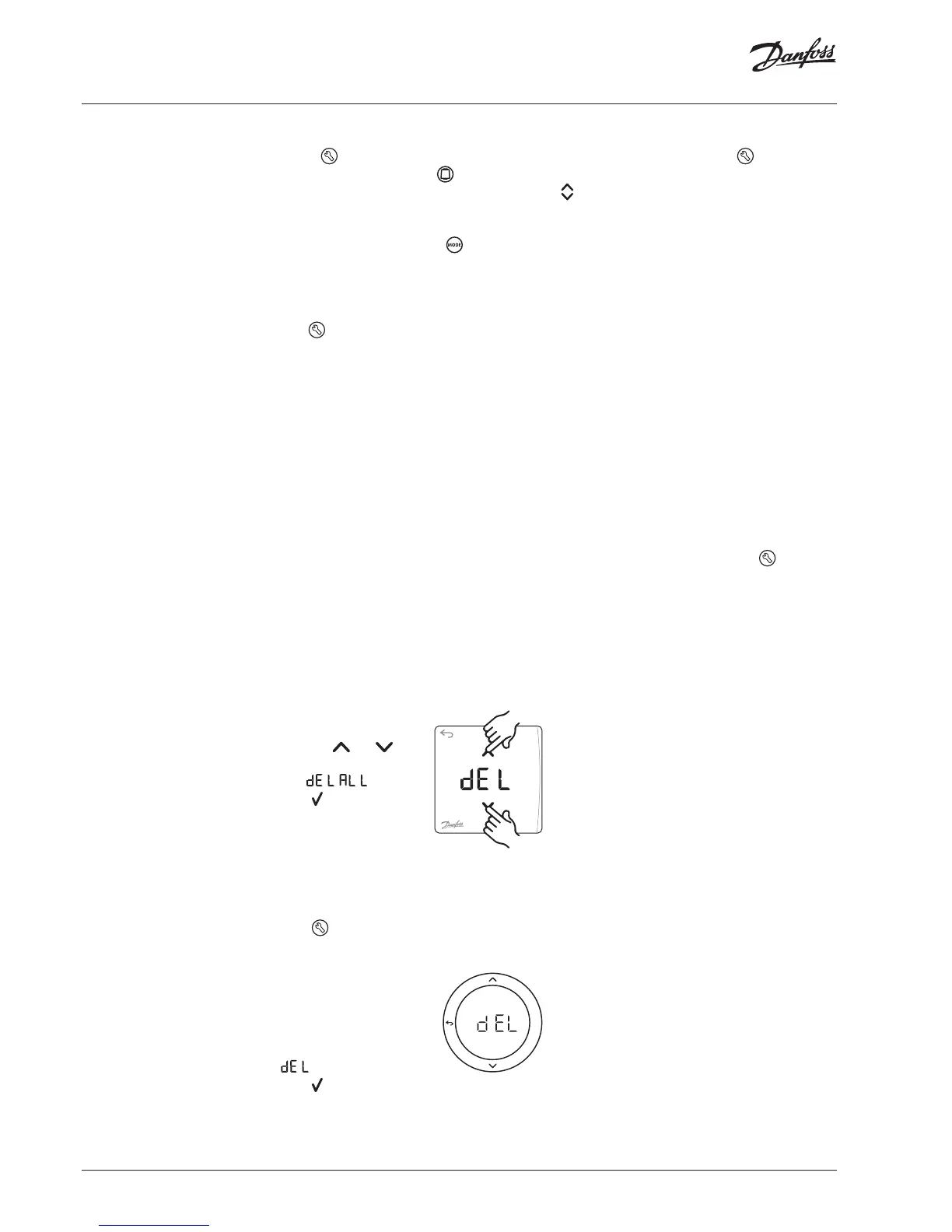
Removing a thermostat
1. On the thermostat, press
and hold
and for 3
seconds until the display
says
.
2. Press
. The thermostat
is now removed from the
system.
Removing an unresponsive App or Radio
Module
If an app or radio module becomes unresponsive
an alarm code will be shown in the Danfoss Icon™
Master Controller 24V display.
Find the defective module and simply unplug the
app or radio module and replace it with a new
one.
OK
Removing a defective thermostat
If a unit in the system becomes defective, it might
be required to remove it from the system.
1. Press
to select UNINSTALL mode.
2. Select the output assigned to the unresponsive
thermostat on the Master Controller.
3. All LED’s on outputs connect-
ed to the unresponsive ther-
mostat will light up and be
selected automatically when
a single output is selected.
ashes on the display.
4. Press
to remove the thermostat from the
system.
 Loading...