M2
M3
M4
M5
LN
LN
APP
Danfoss
230 V
Actuator outputs - 24 V
App
Module
Link
Master
Brown
Blue
Green/Yellow
PWR1 PWR2 RELAY
Radio
Module
Opening of expansion
slot and wiring of
terminals below the
expansion slot shall
only be performed by
a trained electrician.
Risk of electric shock
RISK OF ELECTRIC SHOCK!
Removing lid and installing
230V wires should only
be preformed by a
trained professional.
GB
© Danfoss | FHEC | 2018.06 | 5
VIMCG30F / 088N3678
Installation Guide Danfoss Icon™ Master Controller 24 V
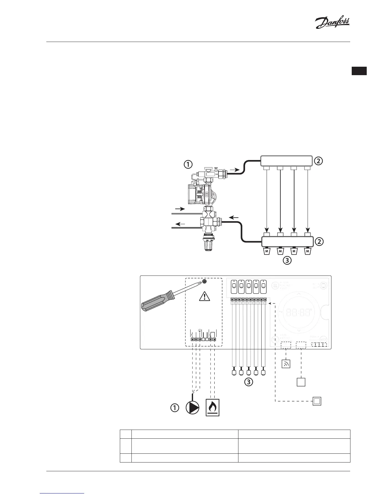
Upon rst installation the system is congured as
a standard oor heating system. In this application
the circulation pump output and the potential
free relay are both activated when there is a heat
demand.
Both the boiler relay and the pump output has a
delay of 180 seconds in this application to ensure
there is ow through the circuits before the boiler
is activated.
The use of mixing shunt, connection of circulation
pump to Danfoss Icon™ Master Controller 24V
and use of boiler relay is optional, depending on
application and available components.
To congure the Danfoss Icon™ Master Controller
24V system for other applications an Expansion
Module (code no. 088U1100) is required.
Application
Application, Basic
• 2-pipe system
• Mixing shunt (optional)
Parts list
1 1 pc. Danfoss FHM-Cx mixing shunt (optional) Part no. 088U0093/0094/0096
2 1 set Danfoss Manifold Part no. 088U05xx (FHF), 088U06xx (BasicPlus) or
088U07xx (SSM)
3 x pcs. TWA-A 24 V thermal actuators Part no. 088H3110 (NC), 088H3111 (NO)