GB
© Danfoss | FHEC | 2018.06 | 11
VIMCG30F / 088N3678
Installation Guide Danfoss Icon™ Master Controller 24 V
Er11 Communication lost to Expansion Module. Check that Expansion Module is slidded
fully into place.
Er12 Actuator defective.
The defective actuator output is ashing.
Replace actuator.
Er14 A Danfoss Icon™ Master Controller cannot
be included as (become) a Slave Controller
because one or more room thermostats,
repeaters or Danfoss Icon™ Master Con-
troller 24V have already been included.
This Danfoss Icon™ Master Controller 24V
has to be factory reset to become a Slave
Controller. (See description in chapter
”Reset or replace a Danfoss Icon™ Master
Controller).
Er16: This application requires a specic actua-
tor output to be available.
You have already assigned this output to
a room thermostat, or the output has not
yet had an actuator tted. Please remove
output from thermostat, it must be
available to the application chosen (or t
actuator — if this was not yet done)
Er17: External PT1000 sensor not tted, or
defective.
Check sensor and replace if necessary.
Hydraulic balance
When using the Danfoss Icon™ Master Controller
24V with PWM+ regulation, the system will auto-
matically balance the circuits.
In heating systems with extreme dierences in
circuit lengths, the automatic balancing might not
be adequate.
In these cases the Danfoss Icon™ Master Controller
24V can help you determine which circuits that are
struggling to get enough ow:
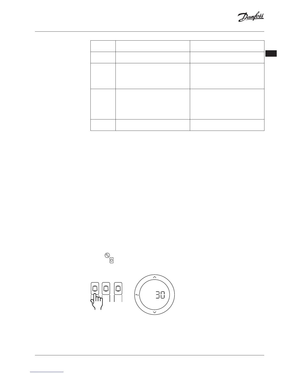
1. Press to select RUN mode.
2. Press an
button to see the average duty
cycle in percentage for the selected circuit.
1 2 3
OK
When pressing the output button the average
duty cycle is shown in the display of the Danfoss
Icon™ Master Controller 24V.
The duty cycle is shown as the amount of time in
% that the actuator is open during active heating
periods and only when in heating mode as an
average over time.
This feature can help determine if one or more
rooms have diculty receiving enough ow or
eect to reach optimal comfort.
The room with the highest duty cycles is the one
that calls for the highest ow. If this room has
problems reaching the desired room setpoint
temperature, the following steps can help give this
room more ow/heating capacity:
1. Increase the ow for the room with the high-
est duty cycle, using the pre-setting valve
on the manifold -> set to maximum ow on
pre-setting valves for this room’s outputs.
2. If the room with the highest duty cycle is
already at maximum ow, instead reduce the
ow for the outputs that show the lowest
duty cycle (these do not need as much ow).
3. If none of the above is enough to reach the
desired room temperature, increase the total
ow, by setting a higher ow on the circula-
tion pump.
4. As a last resort increase the supply tempera-
ture into the system.
Note! By installing an Expansion Module in the Dan-
foss Icon™ Master Controller 24V the system will be
able to automatically adjust the supply temperature
according to heat demand in the rooms.
 Loading...