SFAVM
2
20%
4 6 8 10 12 14 16
40%
60%
80%
100%
110%
I
out
(%)
A1-A3 45°C, A4-A5 40°C
A1-A3 50°C, A4-A5 45°C
A1-A3 55°C, A4-A5 50°C
0
0
130BD640.10
f
sw
(kHz)
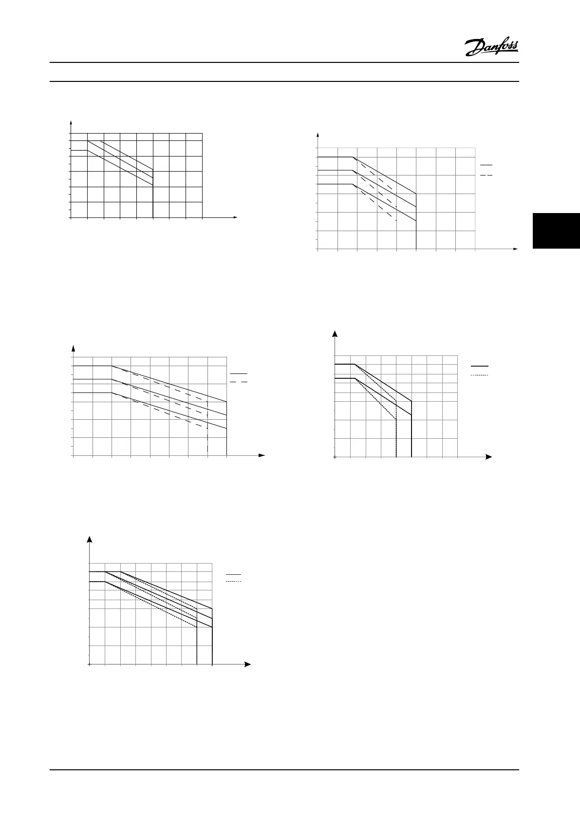
Figure 5.6 Derating of I
out
for Dierent T
AMB, MAX
for Enclosures
Type A, using SFAVM and Maximum 10 m (33 ft) Motor Cable
5.3.2 Derating for Ambient Temperature,
Enclosure Size B
Enclosure B, T2, and T4
60° AVM – Pulse Width Modulation
2
20%
4 6 8 10 12 14 16
40%
60%
80%
100%
110%
f
sw
(kHz)
0
0
I
out
(%)
NO
45°C
50°C
55°C
130BA401.11
B1
B2
Figure 5.7 Derating of I
out
for dierent T
AMB, MAX
for Enclosure
Sizes B1 and B2, using 60° AVM in Normal Overload Mode
(110% Overtorque)
2 4
6 8
20%
10
40%
60%
80%
90%
100%
o
50 C
o
45 C
110%
12 14
16
o
55 C
f
sw
(kHz)
0
0
(%)
l
out
B3
B4
NO
130BB828.10
Figure 5.8 Derating of I
out
for Dierent T
AMB, MAX
for Enclosure
Sizes B3 and B4, using 60° AVM in Normal Overload Mode
(110% Overtorque)
SFAVM – Stator Frequency Asyncronous Vector
Modulation
2
20%
4 6 8 10 12 14 16
40%
60%
80%
100%
110%
f
sw
(kHz)
45°C
50°C
55°C
0
0
I
out
(%)
NO
130BA403.11
B1
B2
Figure 5.9 Derating of I
out
for dierent T
AMB, MAX
for Enclosure
Sizes B1 and B2, using SFAVM in Normal Overload Mode
(110% Overtorque)
2 4
6 8
20%
10
40%
60%
80%
90%
100%
o
50 C
o
45 C
110%
12 14
16
B3
B4
f
sw
(kHz)
0
0
(%)
l
out
NO
130BB832.10
Figure 5.10 Derating of I
out
for dierent T
AMB, MAX
for Enclosure
Sizes B3 and B4, using SFAVM in Normal Overload Mode
(110% Overtorque)
Special Conditions Design Guide
MG20N622 Danfoss A/S © 09/2014 All rights reserved. 117
5 5

 Loading...


