connected to the VLT
®
AQUA Drive is also controlled to
provide a continuous range of system output.
Designated use
The cascade controller options are designed for pump
applications; however, it is also possible to use cascade
controllers in any application requiring multiple motors
congured in parallel.
Operating principle
The cascade controller software runs from a single
adjustable frequency drive with the cascade controller
option. It controls a set of pumps, each controlled by an
adjustable frequency drive or connected to a contactor or
a soft starter.
Additional adjustable frequency drives in the system (slave
adjustable frequency drives) do not need any cascade
controller option card. They are operated in open-loop
mode and receive their speed reference from the master
adjustable frequency drive. Pumps connected to slave
adjustable frequency drives are referred to as variable-
speed pumps.
Pumps connected to line power through a contactor or
soft starter are referred to as xed-speed pumps.
Each pump, variable-speed or xed-speed, is controlled by
a relay in the master adjustable frequency drive.
The cascade controller options can control a mix of
variable-speed and xed-speed pumps.
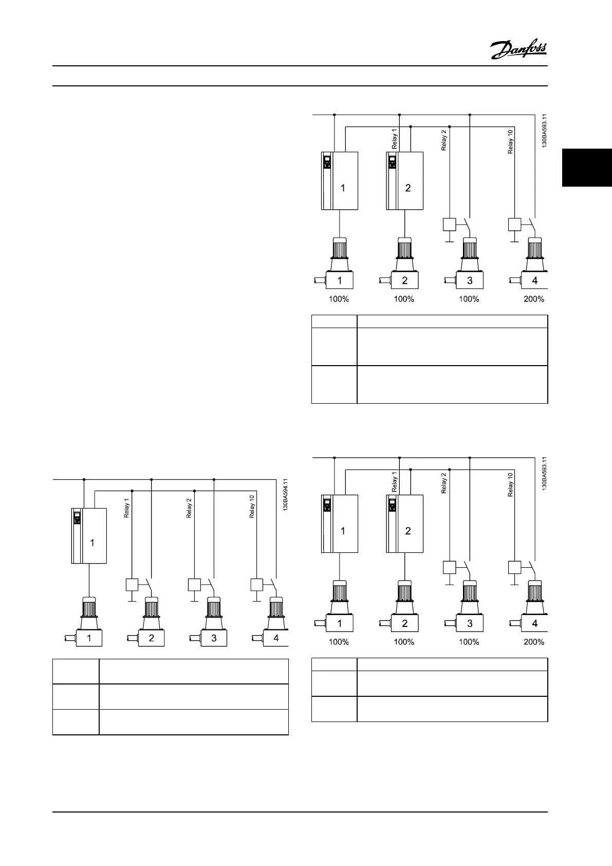
Built-in
1 VSP + 2 FSP
parameter group 25-** Cascade Controller
MCO 101
1 VSP + 5 FSP
parameter group 25-** Cascade Controller
MCO 102
1 VSP + 8 FSP
parameter group 25-** Cascade Controller
Figure 3.27 Application Overview
Built-in
-
MCO 101
1 to 6 VSP + 1 to 5 FSP
(maximum 6 pumps)
parameter group 27-** Cascade CTL Option
MCO 102
1 to 8 VSP + 1 to 7 FSP
(maximum 8 pumps)
parameter group 27-** Cascade CTL Option
Figure 3.28 Application Overview
Built-in
-
MCO 101
6 VSP
parameter group 27-** Cascade CTL Option
MCO 102
8 VSP
parameter group 27-** Cascade CTL Option
Figure 3.29 Application Overview
System Integration Design Guide
MG20N622 Danfoss A/S © 09/2014 All rights reserved. 73
3 3

 Loading...


