A data control byte (BCC) completes the message.
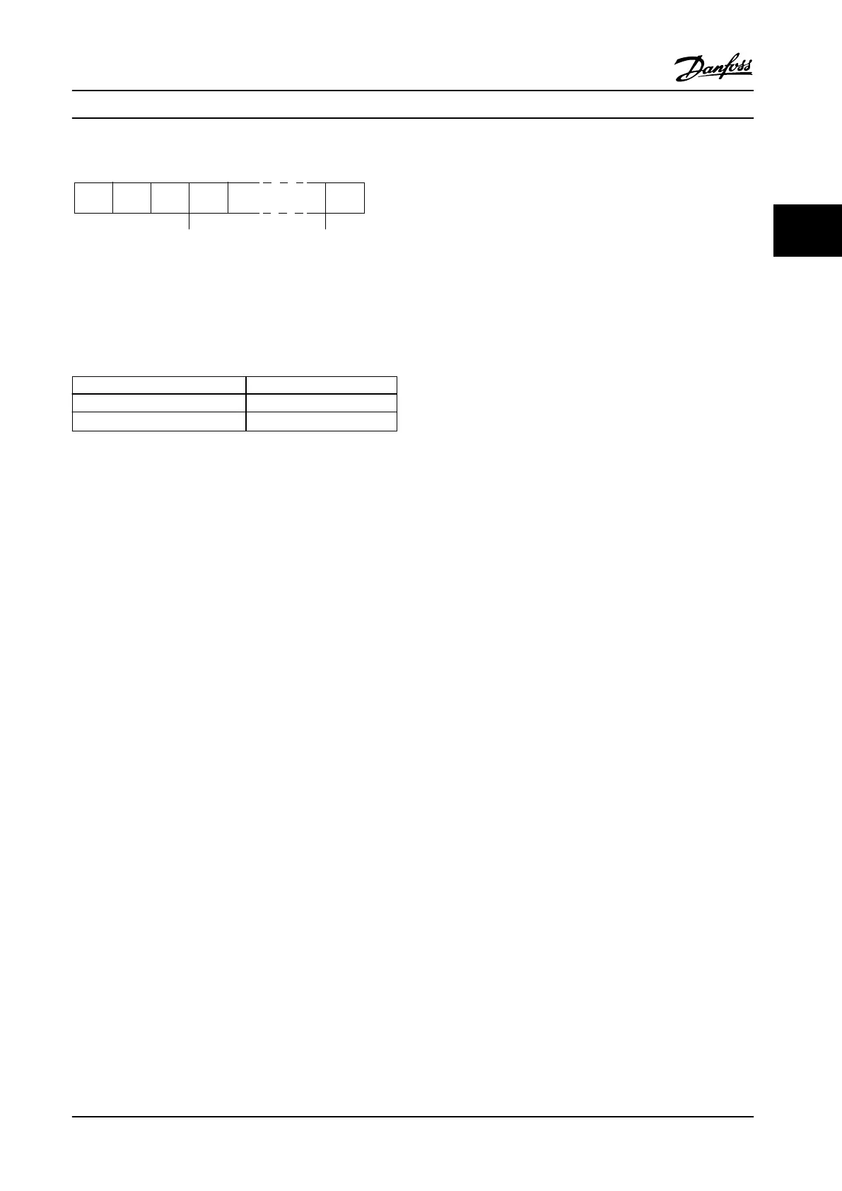
STX LGE ADR D ATA BCC
195NA099.10
Figure 3.46 Message Structure
3.8.7.3 Message Length (LGE)
The message length is the number of data bytes plus the
address byte ADR and the data control byte BCC.
4 data bytes LGE=4+1+1=6 bytes
12 data bytes LGE=12+1+1=14 bytes
Messages containing texts
10
1)
+n bytes
Table 3.27 Length of Messages
1) The 10 represents the xed characters, while n is variable
(depending on the length of the text).
3.8.7.4
Adjustable Frequency Drive Address
(ADR)
Two dierent address formats are used.
The address range of the adjustable frequency drive is
either 1-31 or 1-126.
•
Address format 1-31
-
Bit 7=0 (address format 1-31 active).
-
Bit 6 is not used.
-
Bit 5=1: Broadcast, address bits (0-4) are
not used.
-
Bit 5=0: No Broadcast.
-
Bit 0-4=adjustable frequency drive
address 1-31.
•
Address format 1-126
-
Bit 7=1 (address format 1-126 active).
-
Bit 0-6=adjustable frequency drive
address 1-126.
-
Bit 0-6 =0 Broadcast.
The slave returns the address byte unchanged to the
master in the response message.
3.8.7.5
Data Control Byte (BCC)
The checksum is calculated as an XOR-function. Before the
rst byte in the message is received, the calculated
checksum is 0.
System Integration
Design Guide
MG20N622 Danfoss A/S © 09/2014 All rights reserved. 83
3 3

 Loading...


