VENUE Profile Guide108
Patching Grid
The Patching Grid shows hardware I/O across the top, and
VENUE channels down the left side. The available channel
tabs and choices are determined by the currently selected I/O
tab and Channel type(s). The grid squares represent patch
points between hardware I/O and VENUE mixing channels.
By default, hardware inputs are routed in a 1-to-1 pattern to
input channels. For example, Stage inputs 1–48 appear on In-
put Channels 1–16 (Bank A), 17–32 (Bank B) and so on.
Channel Controls
These controls mirror the controls for the currently selected
channel. For example, when showing Inputs, the Channel
controls let you adjust input gain, polarity, phantom power,
HPF, Direct Out, and basic level without leaving the Patchbay.
Channel Direct Outs
The channel area in the Patchbay provides access to Direct
Out controls.
To adjust Direct Output level from the Patchbay:
1 In the Patching Grid, patch the channel Direct Out to an
available output.
2 In the channel controls, adjust the on-screen Direct Output
encoder.
Visual Indicators and Displays
The Patchbay uses the following visual conventions in all its
pages and tabs.
Unavailable I/O
The Patchbay shows hardware tabs for all possible configura-
tions. The Patchbay indicates I/O that is offline or unavailable
by graying out the columns beneath that device.
Unavailable hardware I/O appear grayed out in the patchbay
and italicized in all routing pop-up lists. It is possible to make
assignments to unavailable hardware I/O.
The VENUE D-Show Standalone software provides additional
display options for hardware I/O (including unavailable I/O).
Assigned I/O
When a hardware connection is assigned, its connection is
dimmed in all Patchbay screens. This lets you see which hard-
ware connections are in use without having to switch back
and forth between Patchbay screens. You can also use the
dimmed column number indicator to jump to the Patchbay
tab for the existing assignment (for more information, see
“Shortcut for Locating Assignments” on page 111).
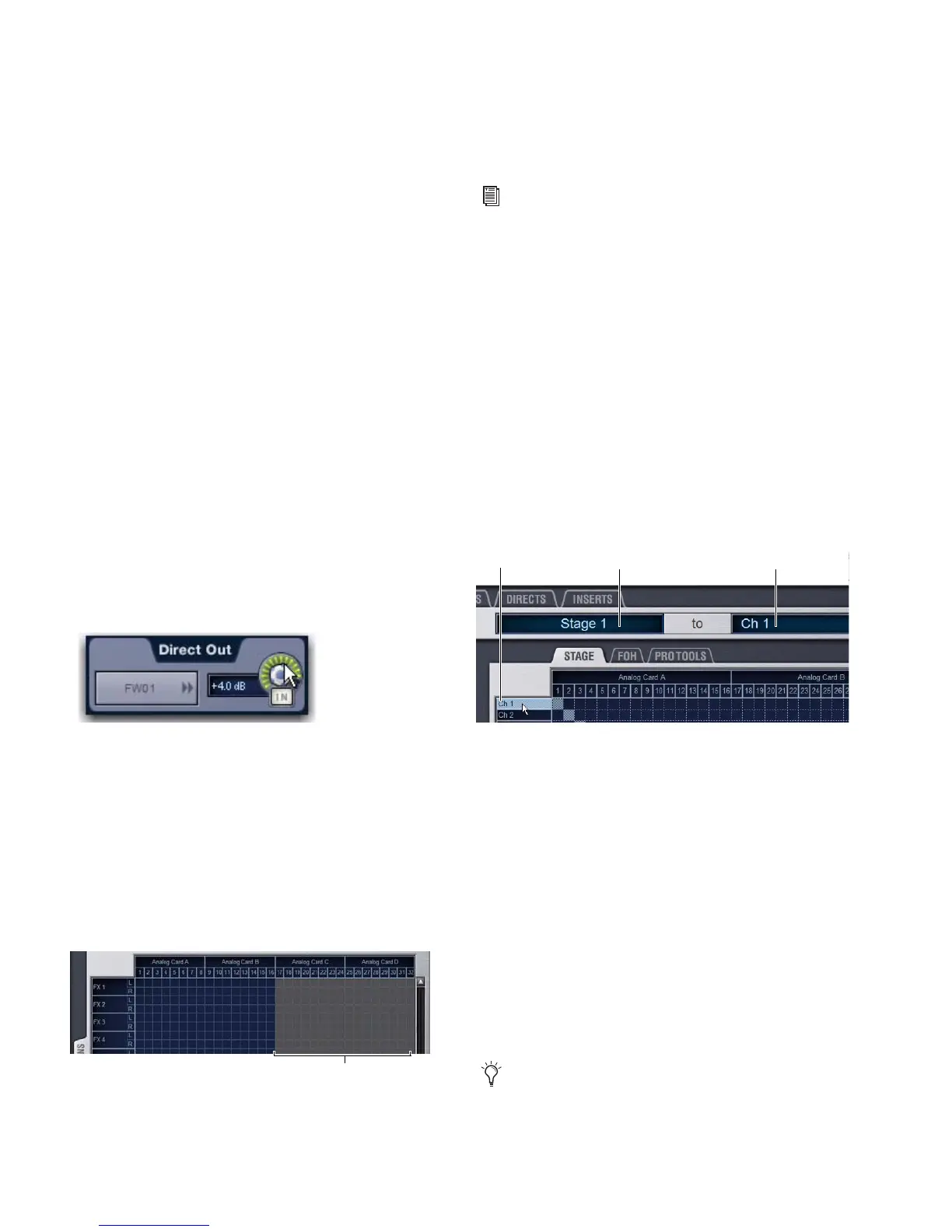
Text Display of Patch Source and Destination
Above the grid tabs are “from” and “to” text display fields that
display the full text names of hardware I/O and channels.
To view full names of a patch source and destination:
Place the cursor over a Channel Name.
If the channel is already routed, its source and destination as-
signments appear directly above the Patching Grid. An aster-
isk at the end of a destination name indicates a multiple out-
put assignment. See “Multiple Input and Output Assignments
in the Patchbay” on page 110.
Naming Channels from the Patchbay
Channel names can be changed from the Patchbay. Channel
names can be up to 32 characters in length. When displayed
on the console, names are abbreviated to fit the display.
To name or rename a channel from the Patchbay:
1 Double-click the channel name.
2 Type a new name and press Enter on your keyboard.
Adjusting Direct Output level from the Patchbay
Unavailable I/O (grayed columns)
See Chapter 24, “Using the Standalone Software.”
Channel source and destination display
When naming channels in the Patchbay, press Tab on the
keyboard to go to the next channel and Shift+Tab to go to
the previous channel.
Source Destination
Channel Name
 Loading...


