Chapter 7: Inputs and Input Routing 73
Activating and Bypassing Inserts
After hardware and plug-in inserts are assigned, they can be
activated and bypassed from the from the ACS section or the
corresponding Input page controls.
To activate or bypass a plug-in insert from the ACS section:
1 Target the channel by pressing its Select switch.
2 Press any of the Plug-In switches in the Insert Processing sec-
tion to activate or bypass the corresponding Insert. The switch
lights when the insert is activated.
To activate or bypass a hardware insert from an input channel or
FX Return:
1 Go to the Inputs page and target the channel.
2 Click the In/Out switch for the HW insert (at the top of the
Inserts section) on the channel. The switch lights when the in-
sert is in-circuit.
Adjusting Input Controls
Input Gain
Input Gain is adjustable from the rotary encoders on each In-
put channel and FX Return. Mic inputs have a gain range from
+10 dB to +60 dB. Analog line inputs and digital inputs have a
gain range from –20 dB to +18 dB.
Gain Guess Feature
The automated Gain Guess function can be used to set a nom-
inal level for a channel based on its incoming signal. When
you press and hold a rotary encoder assigned to input gain,
the system samples incoming signals and automatically sets
the channel gain and pad for a 0 dB reference when the en-
coder is released. Gain Guess follows the current Meter mode
(Peak or RMS).
Gain Indicators
When Gain is displayed on the input encoders, the encoder’s
indicator LED lights to indicate that the gain is set to the de-
fault value (+10 dB for analog inputs, and 0 dB for digital in-
puts). Gain change is indicated by the encoder ring LEDs, and
gain value is shown in the channel display when adjusted.
Setting Input Gain
Gain can be controlled from individual channel strips or from
the ACS section.
To adjust input gain for a channel:
1 Do one of the following:
• In the Encoder Assignment section, press the Gain switch
to assign gain control to the rotary encoders.
– or –
• Target the channel by pressing its Select switch. Gain
control for the channel is assigned to the Gain rotary en-
coder in the ACS Input section.
2 Adjust gain by turning the assigned rotary encoder.
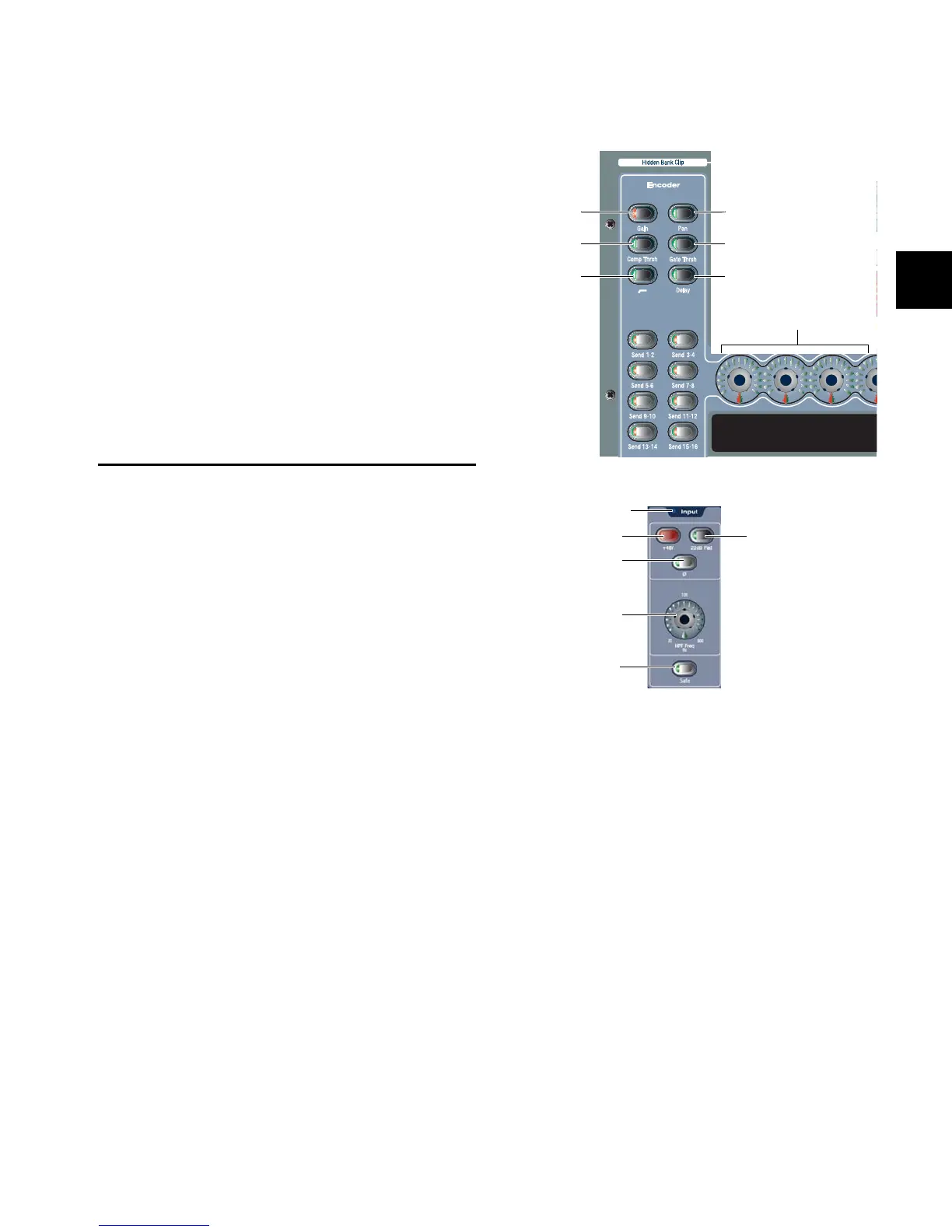
Assignment switches for input channel encoders
Input controls in the ACS
Name display
Gain
Compressor
HPF
Threshold
Pan
Gate Threshold
Delay
Encoders (1–24)
+48 V 20 dB Pad
Input Polarity
Gain
Safe
Clip LED