BACnet MS/TP Communication Data Bus Fundamentals
132 ECLYPSE User Guide
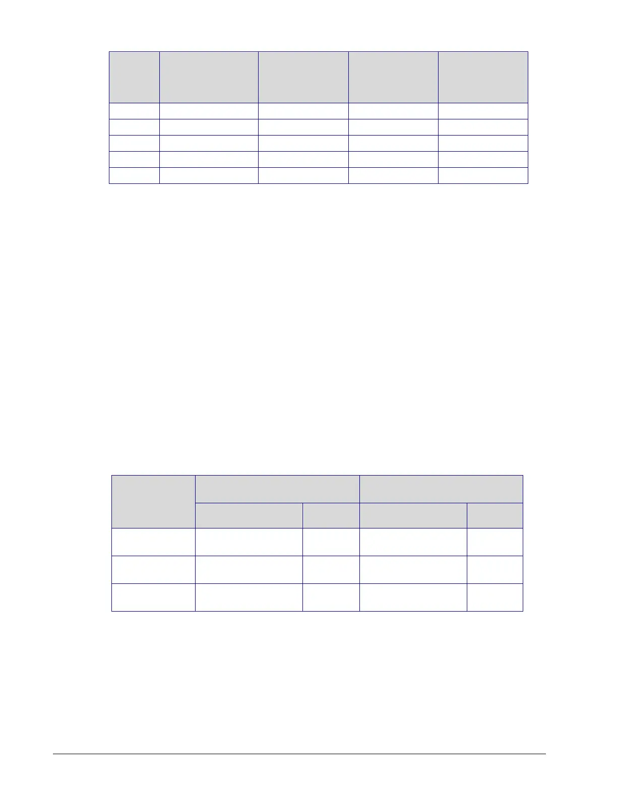
Power Run Total
Cable Length
Maximum
Number of
Devices @ 7 VA
per device
2
Maximum
Number of
Devices @ 10
VA per device
3
Maximum
Number of
Devices@ 15 VA
per device
4
1. See also Metric Conversions for Wire Gauge on page 173.
2. Typical VAV with 1 Allure series sensor (non-CO
2
sensor model) and actuator activated. No external
loads.
3. Typical VAV with 1 Allure series sensor (non-CO
2
sensor model), 2 triac loads (1.6 VA each), 1 analog
output (20 mA), and actuator activated.
4. Typical VAV with 1 Allure series sensor (non-CO
2
sensor model), 4 triac loads (1.6 VA each), 2 analog
outputs (20 mA each), and actuator activated.
OR
Typical VAV with 1 Allure series sensor with CO
2
sensor, 2 triac loads (1.6 VA each), 1 analog output (20
mA), and actuator activated.
5. Device terminals are not capable of accepting two 14 AWG wires (when daisy-chaining devices). Use a
wire nut with a pig tail to make such a connection.
For non-VAV devices, determine the appropriate size transformer for the job as follows:
1. Add up the power requirements of all devices plus all external loads (see About External
Loads on page 131). Multiply the total power needed by a multiplier of 1.3, as a security
margin. For example, to power five devices (15 VA each), the total load is 75 VA
multiplied by 1.3 is 98 VA. Choose a size of transformer just over this amount: For
example, a 100 VA model.
2. When the total load of a number of devices requires a transformer with a rating greater
than 100 VA, use two or more transformers. Ensure that the load to be connected to
each transformer follows the guideline of Step 1 above.
Recommended 24V Power Cable
The table below lists Distech Controls’ recommended power cable.
Table 11-11: Distech Controls Recommended 24V Power Cable
Cable Type
AWG –
Number of
Conductors
Non-Plenum Applications
(FT4)
Plenum Applications
(FT6)
24VAC Power Supply Connection
Use an external fuse on the 24VAC side (secondary side) of the transformer, as shown in
Figure 11-19, to protect all controllers against power line spikes.
The Connected System Controller uses the S terminal as the signal reference point for the
data bus (see Table 11-1 for common device terminal labels).