BACnet MS/TP Communication Data Bus Fundamentals
ECLYPSE User Guide 131
signals from the data bus. Thus it is important to keep the power supply (transformer)
as close to the controller as possible.
Techniques to Reduce Ground Lift
Reduce the impact of ground lift as follows:
Use a heavier gauge wire.
Add more wire runs. Connect these wire runs to the power supply in a star pattern.
For controllers that accept DC power (that is, models without triac outputs): Specify a
24VDC power supply. The continuous and even voltage of a DC power supply makes
more efficient use of the power handling capabilities of a power run. A 24VDC power
supply eliminates the 2.5 multiplication factor associated with the peak AC current being
2.5 times the average RMS AC current. See below.
About External Loads
When calculating a controller’s power consumption to size the 24VAC transformer, you must
also add the external loads the controller is going to supply, including the power
consumption of any connected subnet module (for example, for Allure series communicating
sensors). Refer to the respective module’s datasheet for related power consumption
information.
A controller can support a maximum of two Allure series sensor models equipped with a CO
2
sensor. See Subnetwork Module Compatibility and Supported Quantity Charts on page 136
for how many Allure series communicating sensors are supported by a given controller
model. The remaining connected Allure series sensor models must be without a CO
2
sensor.
Transformer Selection and Determining the Maximum Power Run Length
For the ECY Series, see the calculator spreadsheet available for download from our website
to determine the power requirements and supported quantities of connected subnet
modules: ECLYPSE Selection Tool.xlsm
Distech Controls’ 24V-powered devices are Class 2 Products. To conform to
Class 2 installation requirements, only use transformers of 100VA or less to power
the device(s).
It is recommended to wire only one controller per 24VAC transformer.
For VAV devices, if only one 24VAC transformer is available, determine the maximum
number of daisy-chained VAVs that can be supplied on a single power cable supplied by a
100 VA transformer, according to the controller’s expected power consumption including
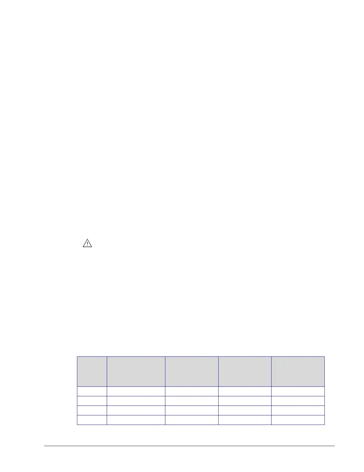
external loads, the cable’s wire gauge, and the total cable length from the following table.
Any installation condition that is outside of the parameters of Table 11-10 should be avoided.
Daisy-chaining controllers is not permitted when a VAV controller’s expected power
consumption including external loads is over 15VA. In this case the controller must be
connected to the 24VAC transformer in a star topology. The transformer must be installed in
close proximity to the controller.
Table 11-10: Maximum Number of 24VAC VAV Devices on a Power Run with a 100
VA Transformer (Daisy-Chained)
Power Run Total
Cable Length
Maximum
Number of
Devices @ 7 VA
per device
2
Maximum
Number of
Devices @ 10
VA per device
3
Maximum
Number of
Devices@ 15 VA
per device
4