Working basis
Service Instructions 869-M PREMIUM - 00.0 - 07/2018 25
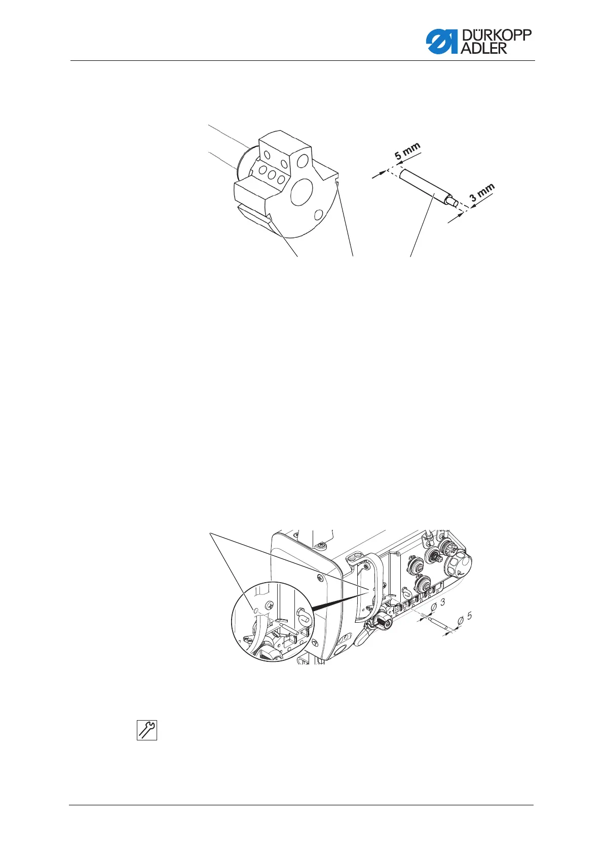
3.6 Locking the machine in place
Fig. 13: Locking the machine in place (1)
For some settings, the machine must be locked in place. To do this, the
locking peg from the accessory pack is inserted into a slot on the arm shaft
crank, blocking the arm shaft.
There are 2 securing positions:
• Position 1: Loop stroke position
• 5 mm end in the large arresting groove (1)
• Setting the loop stroke and needle bar height
• Position 2: Handwheel zero position
• 3 mm end in the small arresting groove (2)
• Setting the handwheel position and checking the top dead center
for the needle bar
Fig. 14: Locking the machine in place (2)
Locking the machine in place
To lock the machine in place:
1. Remove the plug from the locking opening (4).
(1) - Large arresting groove
(2) - Small arresting groove
(3) - Locking peg
(4) - Locking opening
 Loading...