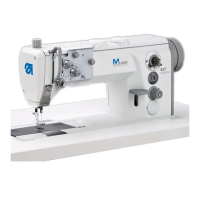
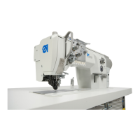
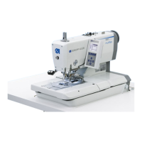
Programming
Service Instructions 869-M PREMIUM - 00.0 - 07/2018 115
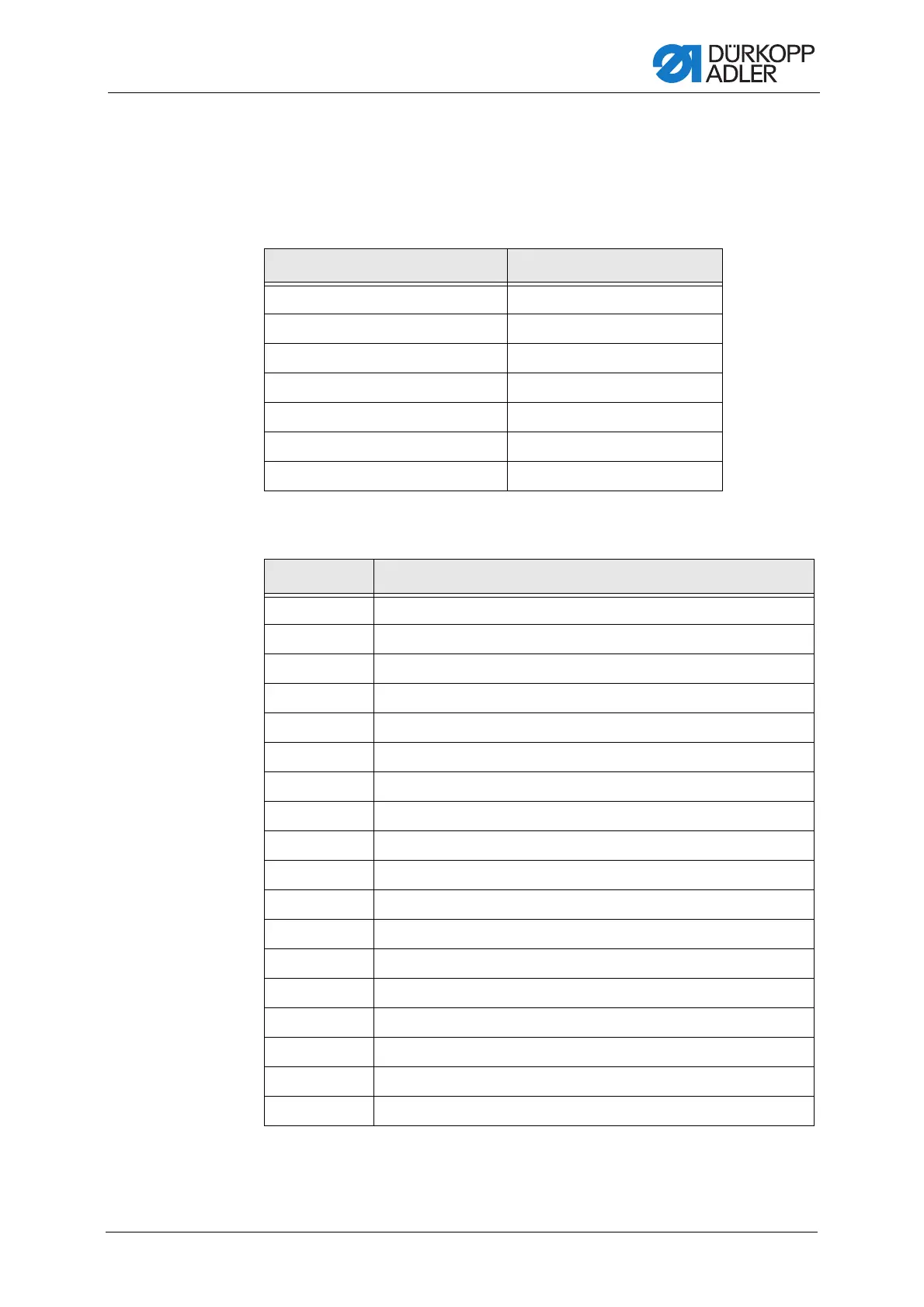
19.7.4 Setting the Output configuration (Output Config)
parameter
Configure and allocate the outputs here. The table shows the outputs and
their allocation. The pins on the circuit board are labeled and must be allo-
cated according to the table, depending on what was connected to the pin.
A mode can be allocated to every output (parameter T 56 00).
The following table lists the modes:
Machine output signal Output
ML (X22) X120B.9
NK (X22) X120B.10
RA (X16) X120B.12
STL (X17) X120B.22
STL(FA) (X18) X120B.23
FL (X15) (X22) X90.12
FF3 OUT (X22) X90.15
Mode Function
0 No function assigned
1 Needle cooling
2 Cleaning signal for the remaining thread monitor
3 Pos 1 (needle down)
4 Pos 2 (top dead center)
5 Motor running signal
6 Puller/seam center guide
7 Sewing foot lift signal
8 Puller
9 Puller pressure
10 Bartack
11 Bartack process
12 Thread cutter
13 In the seam
14 Segment Output 1
15 Segment Output 2
16 Segment Output 3
17 Segment Output 4
 Loading...