Integrated motor
Service Instructions 869-M PREMIUM - 00.0 - 07/2018 89
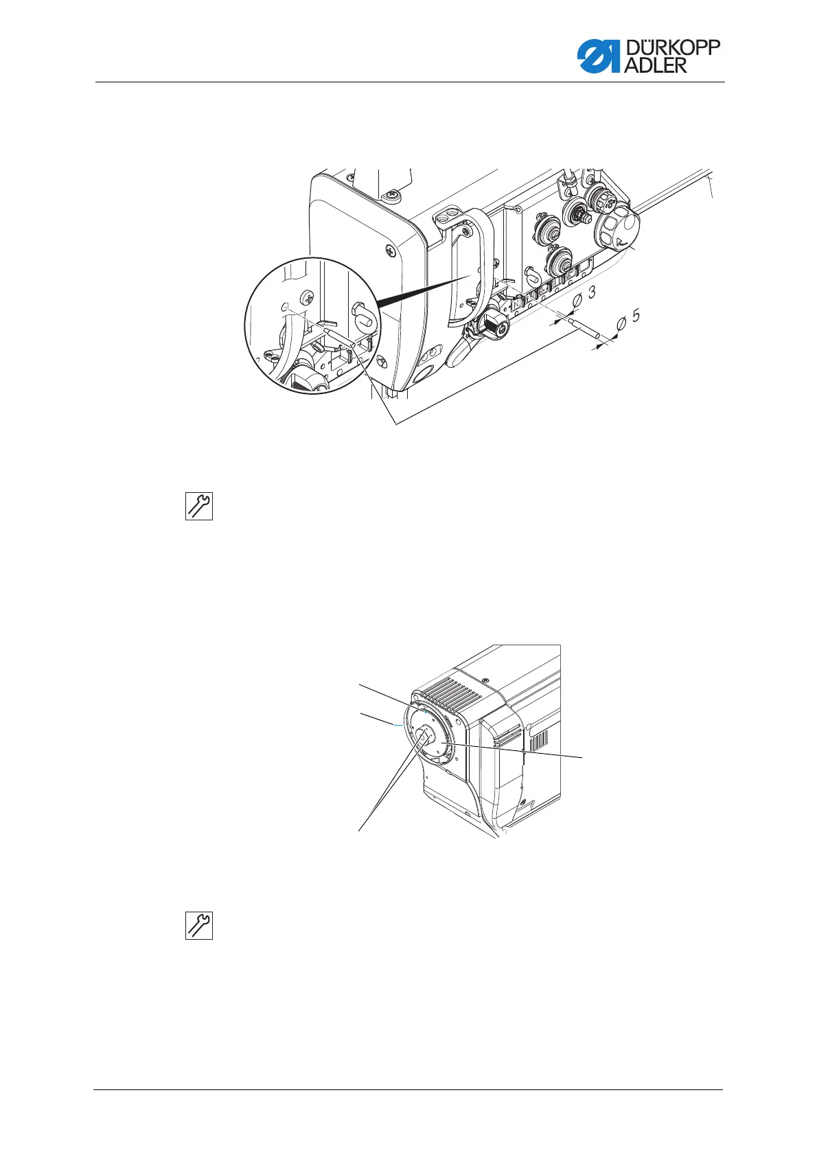
18.3.5 Locking the machine in place
Fig. 78: Locking the machine in place
To lock the machine in place:
1. Lock the machine in place using the locking peg (1) (Ø 3 mm).
The needle is in the top dead center position.
18.3.6 Assembling the handwheel flange
Fig. 79: Assembling the handwheel flange
To assemble the handwheel flange:
1. Attach the handwheel flange (4) so that the two markings (1), (2) are
in line.
2. Screw both threaded pins (3) firmly in place.
In doing so, make sure that there is a distance of approx. 0.5 - 1 mm
between the handwheel flange (4) and the cover plate.
(1) - Locking peg
o
(1) - Handwheel flange marking
(2) - Cover marking
(3) - Threaded pins
(4) - Handwheel flange
 Loading...