SV-EMS-220 Installation and Configuration
7-28 SkyView System Installation Guide - Revision K
Tachometer
Tachometer pulses/revolution must be set in the Engine Information Wizard
(SETUP MENU > EMS SETUP > ENGINE INFORMATION).
Dynon Avionics does not sell a tachometer transducer.
Depending upon existing equipment and engine type, you have a few options for connecting
the tachometer inputs on the SV-EMS-220. The following table revisits the SV-EMS-220 pins
that are compatible with RPM sources.
Standard RPM Input Left (10+ volts)
Standard RPM Input Right (10+ volts)
Low Voltage RPM Input Left (2 to 10 volts)
Low Voltage RPM Input Right (2 to 10 volts)
Table 32–SV-EMS-220 RPM Inputs
See the relevant subsections below for your particular method. You may connect different
types of signals to the two different RPM inputs (e.g., p-lead to Standard RPM Left and a 12 volt
transducer to Standard RPM Right).
If a standard RPM input is used, do not connect anything to the low voltage input
of the same polarity (i.e., right or left). If a low voltage RPM input is used, do not
connect anything to the corresponding standard RPM input.
Tachometer transducer
If you have a dedicated tachometer transducer (usually with a 12 volt output), you may simply
connect its output to the Standard RPM Left input on the SV-EMS-220. Ensure that you follow
all recommendations given in the manual for your individual tachometer transducer.
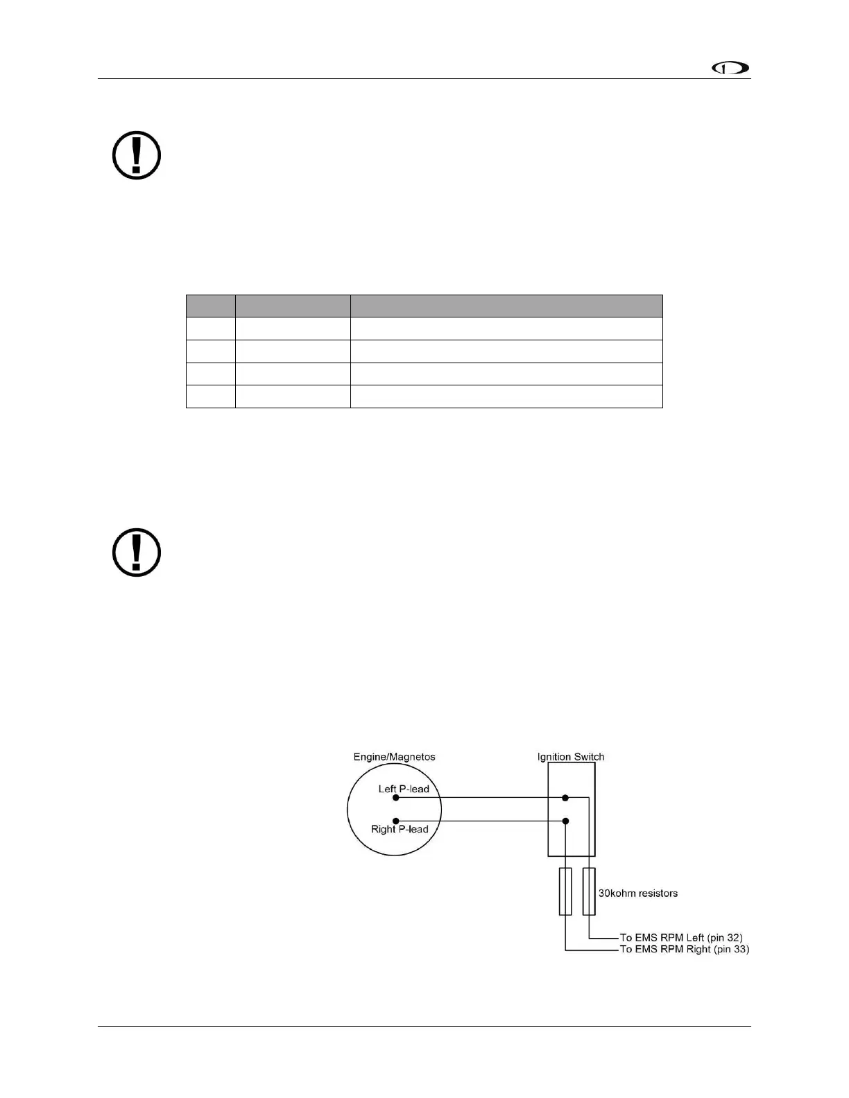
P-lead pickoff (Lycoming and Continental)
If you do not have a dedicated
tachometer pickoff, you must
follow the instructions below.
Use the two included 30 kΩ
resistors (color bands: orange,
black, brown, red, brown; connect
in either direction) to attach left
and right P-leads to the standard
RPM Left and RPM Right inputs on
the SV-EMS-220. Connect them as
shown in Figure 27. It is important
to connect each resistor as close
Figure 27–Magneto Pick Off