SV-GPS-250 Installation and Configuration
8-2 SkyView System Installation Guide - Revision K
Physical Installation
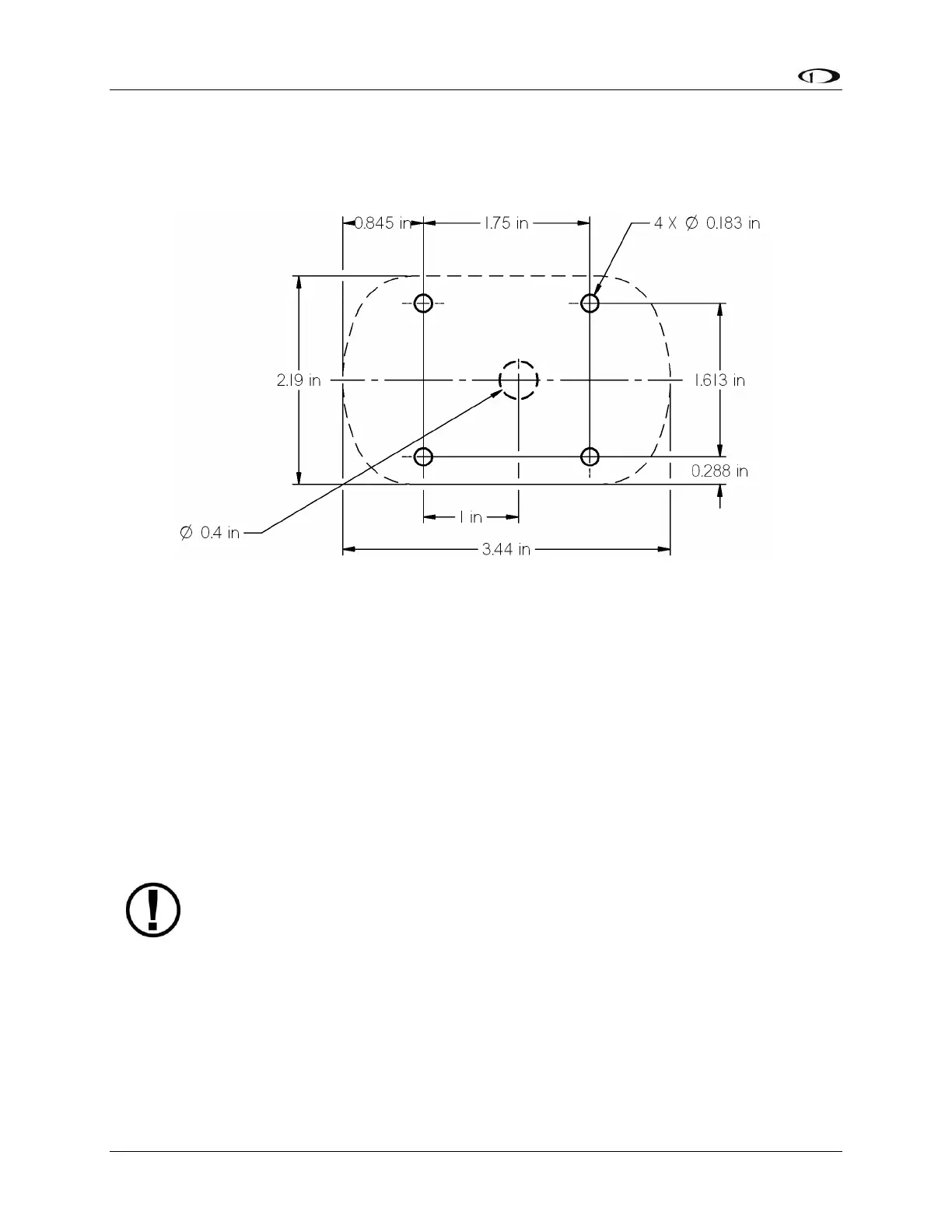
The diagram below shows the mounting dimensions of the GPS module. Note that it utilizes a
common bolt pattern found in much of general aviation.
Figure 48–SV-GPS-250 Mounting Dimensions
Mounting hardware is not included. The SV-GPS-250 is designed to work with #8 fasteners with
100 degree countersunk heads. The use of nut plates is recommended for convenience, but
other hardware can be used if space allows. Specific hardware selection is determined by the
installer.
We recommend you use weather sealant around the fastener heads to keep moisture from
entering the aircraft through the mounting holes. The module itself is sealed and includes a
rubber gasket that seals the inner wire hole. It also allows the module to be mounted on slightly
curved surfaces. For extra protection, you may use weather sealant around the outside of the
SV-GPS-250 module where it meets the skin of the aircraft.
Serial Connection
SkyView uses the SV-GPS-250 device set to POS 1 as its primary position source.
The SV-GPS-250 includes 18 feet of twisted wire for a serial connection to the SkyView display
via the display. This wire may be trimmed or lengthened as needed to suit the installation.
The color of the SV-GPS-250 wires matches the colors of the wires of the main display harness
that are intended for the GPS serial connection. The following table contains information
regarding the wires.