System Planning
2-16 SkyView System Installation Guide - Revision K
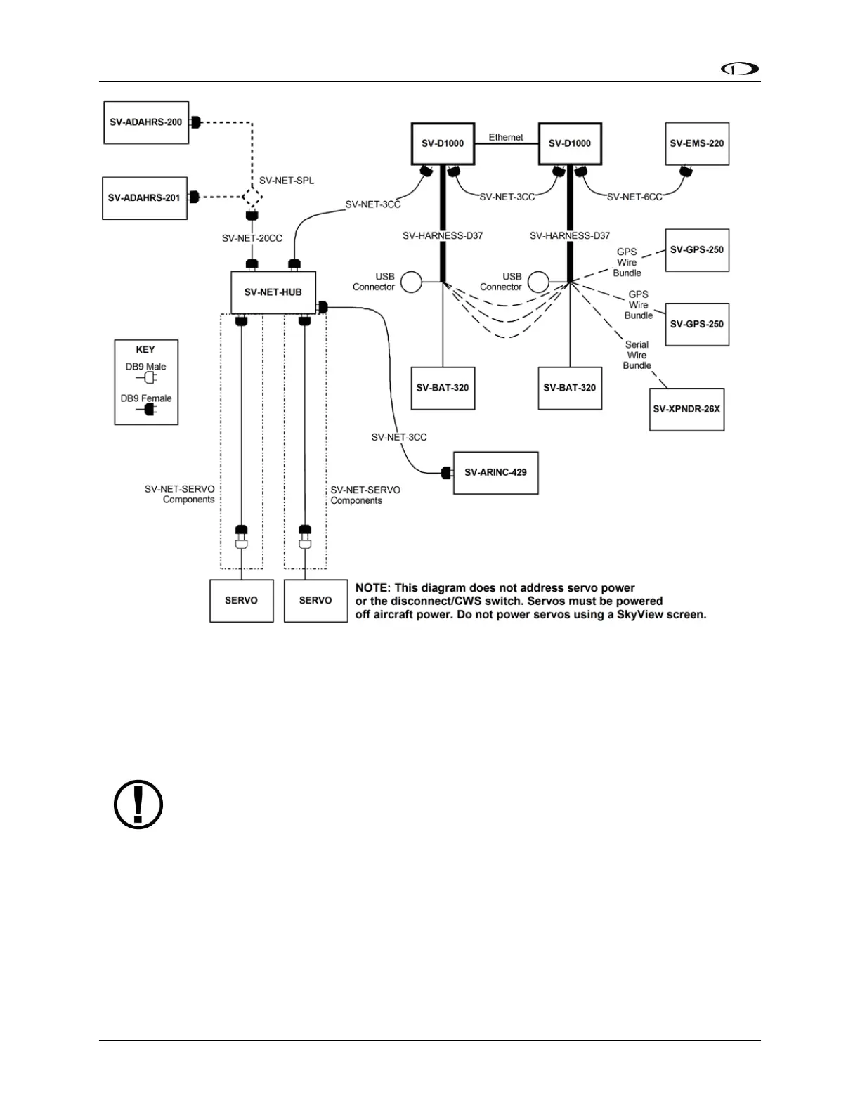
Figure 8 - SkyView System with Two Redundant Displays, One EMS, Two Backup Batteries (One per Display),
Two Redundant GPS, Two Redundant ADAHRS, Two Servos, and one Transponder using a hub (recommended
installation method)
Note, that in Figure 8, each SV-GPS-250’s power, ground, and output wires are
connected to both displays on different serial ports. The primary SV-GPS-250
should be connected to serial port 5 on each display. The secondary SV-GPS-250
should be connected on another serial port on each display.
Additionally, if there are both multiple displays and multiple SV-GPS-250 units in
the system, power for the secondary GPS should be sourced from the GPS power
wire on the second display – in other words, each SV-GPS-250 should receive
power from a different display. Reference the SV-GPS-250 Installation and
Configuration Section for more information on this configuration.
HSI Requirements
The SkyView HSI overlay on the PFD’s DG requires an external GPS (e.g., Garmin X96) or NAV
(e.g., Garmin SL30) radio. It can also be generated by SkyView when its Navigation Mapping