SV-EMS-220 Installation and Configuration
7-44 SkyView System Installation Guide - Revision K
contact connects to a ground common to the SkyView system. The voltage on the general
purpose inputs must not exceed 15 volts.
General Purpose Thermocouple
You may configure the SV-EMS-220 to monitor two J or K type thermocouples in addition to the
12 thermocouples available on the SV-EMS-220’s D25. Dynon Avionics does not supply a
specific general purpose thermocouple probe for this purpose. However, our standard EGT and
CHT probes will work, as will any other J or K type thermocouple.
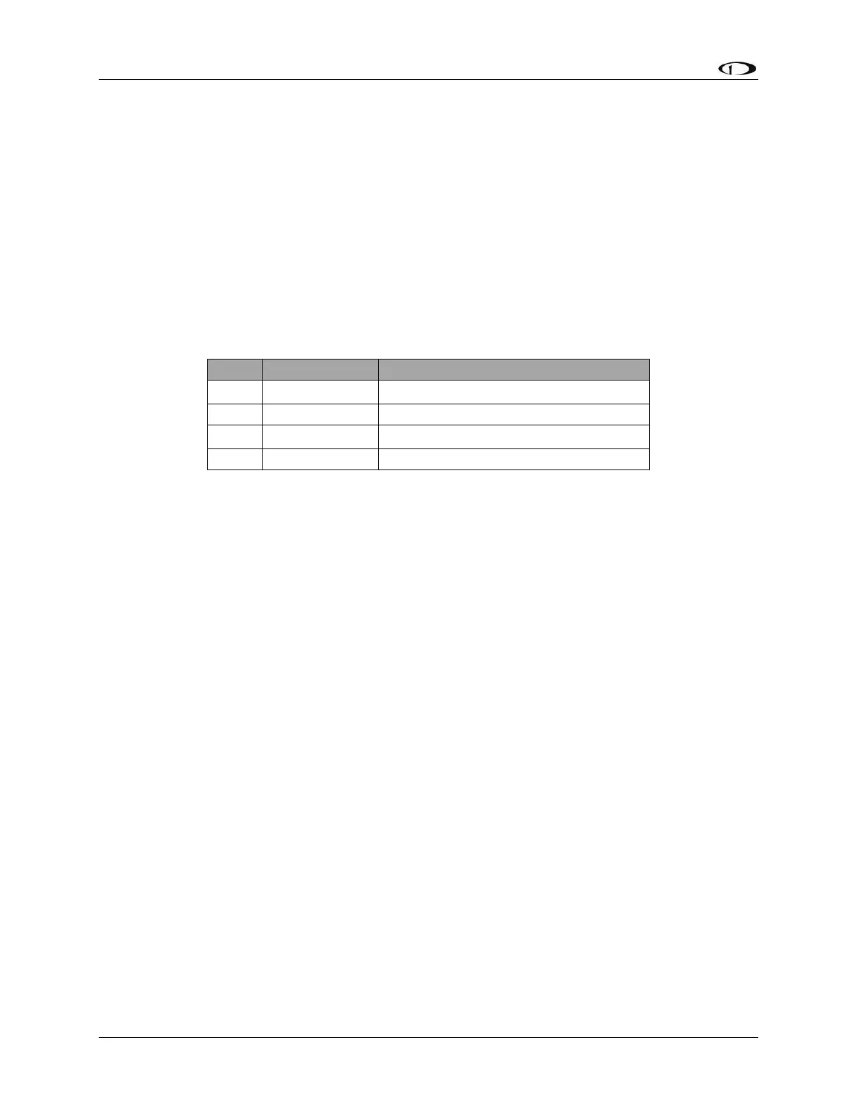
The following table revisits which SV-EMS-220 pins are compatible with general purpose
thermocouples.
General Purpose TC Input 1+
General Purpose TC Input 1-
General Purpose TC Input 2+
General Purpose TC Input 2-
Table 36–SV-EMS-220 D37 General Purpose Thermocouple Pins
If you use the second general purpose thermocouple input on pins 36 and 37, it is necessary to
remove the blue and green wires from these pins on the EMS 37-pin Main Sensor Harness.
Dynon Avionics sells both J and K type thermocouple wire which may be used to connect the
desired thermocouple to the SkyView. Ensure you order the correct wire type for the
thermocouple you intend to use. Crimp a female D-sub pin on the end of each wire, and plug
them into the SV-EMS-220’s EMS 37-pin Main Sensor Harness D37. Polarity is important, so
ensure that you are routing the positive side (yellow for K-type; white for J-type) of the
thermocouple to pin 27 or pin 36 on the 37-pin harness, and the negative side to pin 28 or pin
37.
External EMS Warning Light
SV-EMS-220 D37 pin 29 can be wired and configured as an External Alarm Light
To wire EMS D37 pin 29 as an External Alarm Light, you may connect any standard LED or
incandescent lamp (1.5 watts maximum), used during EMS-related “red” warning alarm
conditions. Ensure that the LED or lamp is designed for the voltage of your system. Mount it to
your panel according to its recommendations. Connect one of the lamp’s leads to your plane’s
power. Connect the other lead to pin 29 on the SV-EMS-200 37-pin wiring harness. During an
alarm condition, this pin is connected to ground, causing current to flow through the lamp.
Aircraft Spruce P/N 17-410 is an example of a light that will work for this application. An LED
and resistor in series will also suffice. If you use an LED as the indicator, you must choose a
resistor that delivers the appropriate current to the LED, and can accommodate the power