SV-XPNDR-26X Installation, Configuration, and Testing
11-12 SkyView System Installation Guide - Revision K
A dual crimp style TNC connector can be completed using a wide range of commercial crimp
tools (for example the Tyco 5-1814800-3). The die apertures for the inner pin and the outer
shield should be approximately 1.72 mm and 5.41 mm respectively.
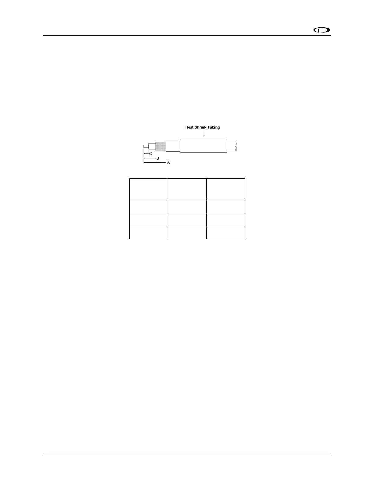
Strip back the coax cable to the dimensions in the table, as shown in the diagram below.
Slide 25 mm (1 inch) of heat shrink tubing over the cable.
Slide the outer crimp sleeve over the cable – it must go on before securing the center
contact.
Crimp the center contact to the cable.
Insert the cable into the connector – the center contact should click into place in the
body, the inner shield should be inside the body of the connector and the outer shield
should be outside the body.
Crimp the outer sleeve over the shield.
Slide heat shrink tubing forward (flush to connector) and heat to shrink the tubing.
Transponder-Related SkyView Display Settings
Serial Port Setup
Before the TRANSPONDER SETUP menu can be accessed, the SV-XPNDR-26X needs to be set up
as a serial device on each SkyView display on the system. To accomplish this:
Go to SETUP MENU > LOCAL DISPLAY SETUP > SERIAL PORT SETUP.
Navigate to the serial port that you physically connected the transponder module to in
the previous steps.
Select either “Dynon 261 Transponder” or “Dynon 262 Transponder” as appropriate for
the module you own. Note that other fields are automatically configured and cannot be
changed. Press ACCEPT.