SV-EMS-220 Installation and Configuration
7-38 SkyView System Installation Guide - Revision K
Ammeter Shunt
The ammeter shunt should be mounted so that the
metal part of the shunt cannot touch any part of the
aircraft. The ammeter shunt can be installed in your
electrical system in one of three locations as shown in
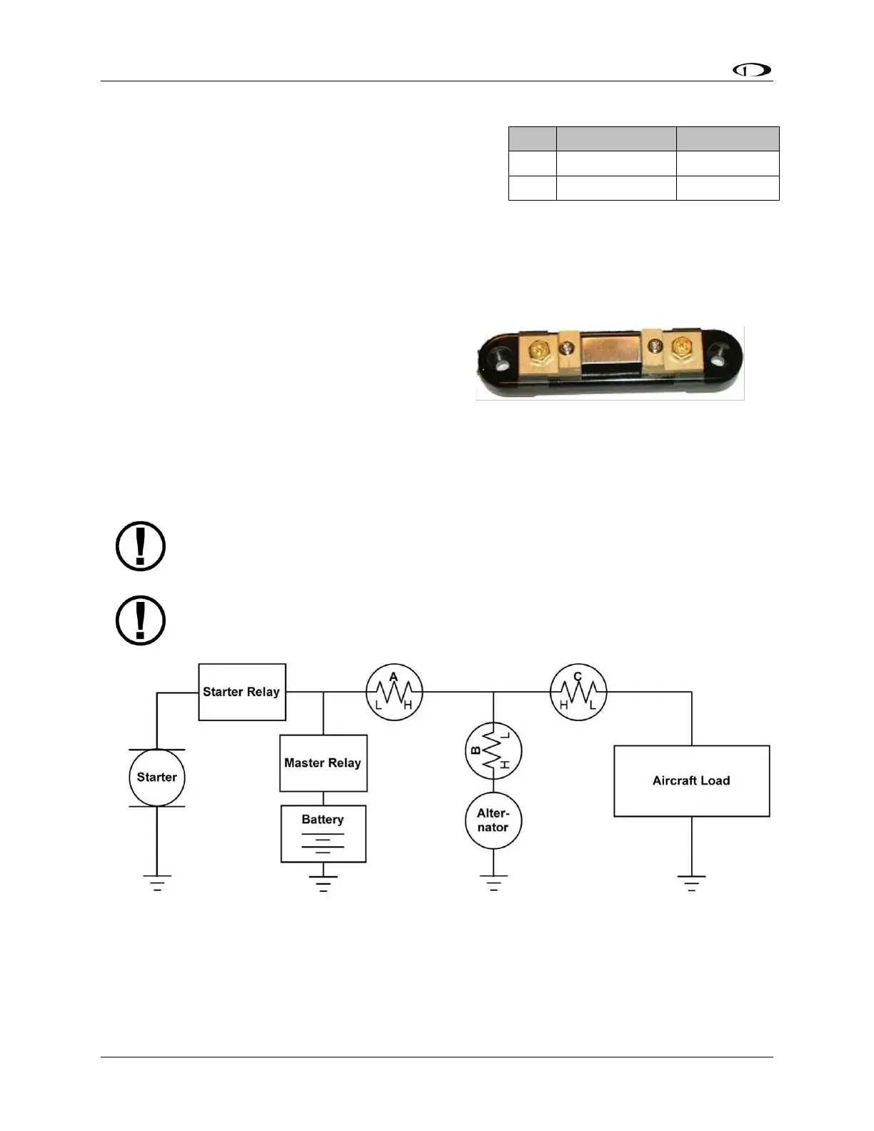
Figure 37.
If you have a Vertical Power VP-X system in your
aircraft, use either position A or position B. Position C is not useful in a VP-X installation
because the VP-X measures aircraft loads directly.
Position A–Ammeter indicates current flow into
or out of your battery. In this position, it will
show both positive and negative currents
(i.e., -60 amps to +60 amps).
Position B–Ammeter indicates only the positive
currents flowing from the alternator to both
the battery and aircraft loads. (0A-60A)
Position C–Ammeter indicates the current flowing only into the aircraft loads. (0A-60A)
Note that the ammeter shunt is not designed for the high current required by the
starter and must not be installed in the electrical path between the battery and
starter.
The Ammeter Shunt packaging may be marked 40mV/40A. However, Dynon rates
the shunt for up to 60A loads.
Figure 37–Recommended Amps Shunt Locations (simplified electrical diagram)
Use two ¼” ring terminals sized appropriately for the high-current wire gauge you will be
routing to and from the ammeter shunt. Cut the wire where you would like to install the
ammeter shunt. Strip the wire and crimp on the ring terminals. Using a Phillips screwdriver,