Autopilot Servo Installation, Configuration, and Calibration
SkyView System Installation Guide - Revision K 10-9
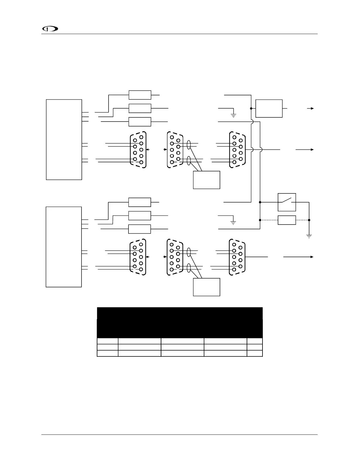
Autopilot System Electrical Installation
Figure 55 provides an overview of the autopilot electrical system. Note that SkyView supports
up to two servos.
Female DB9
Male DB9
YELLOW
GREEN
BLUE
WHITE/BLUE
SERVO
(SV32, SV42,
or SV52)
1
5
6
9
Female DB9
CONNECT
1
5 5
6
9 9
WHITE/BLUE
WHITE/GREEN
BLUE
GREEN
1
6
To SkyView
Network
SPLICE
SPLICE
SPLICE
RED
BLACK
BLACK - 20 AWG - To Aircraft Ground
WHITE/GREEN
Female DB9
Male DB9
YELLOW
GREEN
BLUE
WHITE/BLUE
SERVO
(SV32, SV42,
or SV52)
1
5
6
9
Female DB9
CONNECT
1
5 5
6
9 9
WHITE/BLUE
WHITE/GREEN
BLUE
GREEN
1
6
To SkyView
Network
SPLICE
SPLICE
SPLICE
RED
BLACK
BLACK - 20 AWG - To Aircraft Ground
WHITE/GREEN
Pilot-accessible
Disengage/CWS button
(Normally open, momentary)
Usually mounted to the stick
5 kohm
Optional resistor for
broken disengage
detection
Twisted Pair
8-10 twists/foot
Twisted Pair
8-10 twists/foot
YELLOW - To Disengage/CWS Button
YELLOW - To Disengage/CWS Button
(halve the current for 24 volt systems)
Engaged,
holding,
100% torque
Engaged,
moving,
100% torque
Unit
SV32 0.10 0.80 1.33 amps
SV42 0.10 1.11 2.03 amps
SV52 0.10 1.52 2.80 amps
- SERVO CURRENT DRAW AT 12 VOLTS -
Pilot accessible
servo power
switch/breaker
RED - 20 AWG - To Servo Power Switch/Breaker
RED - 20 AWG - To Servo Power Switch/Breaker
To Aircraft
Power
(10 to 30 volts)
Figure 55–SkyView Autopilot System Electrical Installation Overview (All Connectors Rear View)
The following sections describe the electrical installation of each subsystem in detail.