Autopilot Servo Installation, Configuration, and Calibration
10-10 SkyView System Installation Guide - Revision K
Servo Electrical Installation
Dynon Avionics’ servos are supplied with 7 unterminated wires, each about 8” in length. We
recommended that you use the SV-NET-SERVO (one per servo) network cabling kit when
installing servos; however, it is ultimately the responsibility of the installer to decide on
connectors and associated wiring.
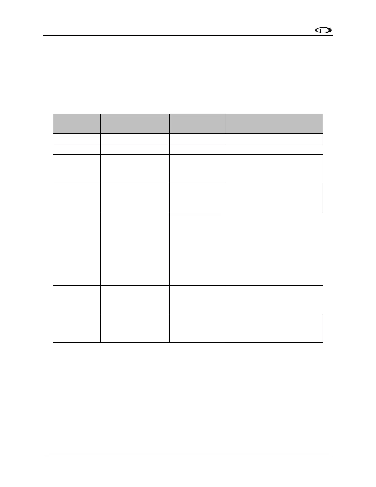
Table 40 describes servo wire colors and functions.
Connected in parallel with
other SkyView Network
devices
Connected in parallel with
other SkyView Network
devices
AP
Disengage/Control
Wheel Steering
(CWS) Button
Connected through a
normally-open pushbutton
switch to Ground (disengages
AP when button is pushed). If
two servos are installed, the
yellow wire from each servo is
connected in parallel to a
single pushbutton.
Connected in parallel with
other SkyView Network
devices
Connected in parallel with
other SkyView Network
devices
Table 40–Detailed Servo Wiring
*Reference the Power Consumption Section of the System Planning Chapter for details
regarding servo current consumption at 12 and 24 volts DC.
Circuit Breaker/Switch
We recommend that electrical power for the all servos be protected with an appropriately sized
circuit breaker or switch that is accessible to the pilot while in flight.