Accessory Installation and Configuration
14-12 SkyView System Installation Guide - Revision K
harness (reference the SV-D700 / SV-D1000 Electrical Installation Section for details on which
pins to use). Also ensure that the display and the Encoder Converter Module share a ground.
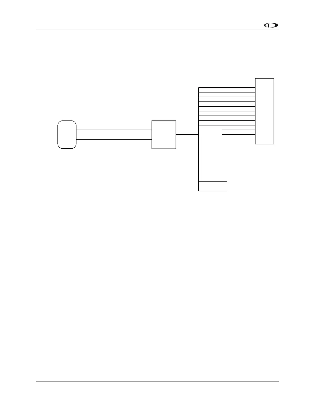
Figure 85 illustrates the basic electrical connection between the SkyView display and the
Encoder Converter module.
TX
GND
Green Wire
Black Wire
SkyView Display Serial Transmit
Shared Ground
Encoder Converter
Module
SkyView Display
DB37 Connector
A1
A2
A4
B1
B2
B4
C1
C2
C4
D4
Strobe
Yellow
Green
White/Blue
Blue
Orange
White/Red
White/Green
White
White/Black
Unconnected
Unconnected
Transponder
Red
Black
10-30 volts
Ground
The Encoder Converter Module
is compatible with all SkyView
display serial ports.
Figure 85–Encoder Converter Module Electrical Connections
Serial Port Setup–DYNON CONVERTER Format
Enter the Serial Port Setup Menu (SETUP MENU > LOCAL DISPLAY SETUP > SERIAL PORT SETUP)
on each display and configure the appropriate serial port for use with the Encoder Serial-to-
Gray Code Converter module with the following settings:
SERIAL # IN DEVICE: NONE
SERIAL # IN FUNCTION: NONE
SERIAL # IN/OUT BAUD RATE: 1200
SERIAL # OUT DEVICE: DYNON CONVERTER
Capacitance-to-Voltage Converter Installation and Configuration
Dynon Avionics’ Capacitance-to-Voltage Converter (Dynon P/N 100654-000) is suitable for
general use with most capacitive plate fuel level sensors. It accepts an input via a female BNC
and outputs a DC voltage signal that can be read by the SV-EMS-220. It requires 10 to 15 volts
DC for power and draws minimal current. We recommend that you connect the Capacitance-to-
Voltage Converter to the SV-EMS-220 for power as shown in the table below. It will also work
properly when connected directly to standard 12 volt DC aircraft power. If your aircraft runs on
24 volt DC power, you must connect the Capacitance-to-Voltage Converter to the SV-EMS-220
for its power source. Voltage inputs higher than 15 volts DC will damage the device.