Accessory Installation and Configuration
SkyView System Installation Guide - Revision K 14-11
Transponder Wiring
Wire the Encoder Converter signals to their respective connections on your Mode-C
transponder according to Table 46. Mode-C transponder pin-outs vary from device to device. To
find the correct pin-out, look at the manual for your transponder or contact its manufacturer.
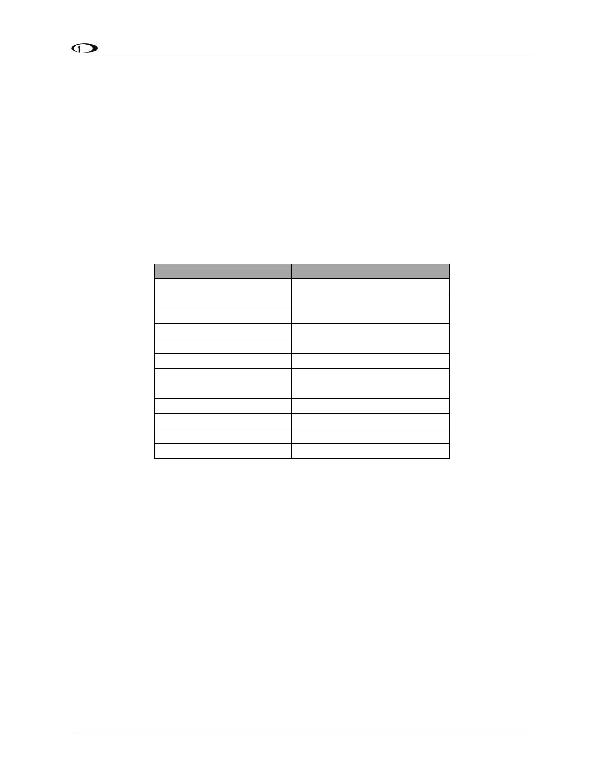
The table below details which color wire should be connected to each Transponder pin. All of
the wires listed in the table leave one end of the Encoder Converter in a single bundle. If your
transponder has a switched power output, connect this to the power inputs on the Encoder
Converter. If your transponder does not include this switched power output, the Encoder
Converter power connections should be made directly to your switched avionics power. Ensure
that all avionics power is off before performing the wiring step of this installation.
If your Altitude Transponder has either a strobe signal or a D4 pin, leave these pins
unconnected.
Encoder Converter Wire Color
Power (10 to 30 volts DC)
Table 46–Transponder to Encoder Converter Wiring
The Gray code output of the Encoder Converter reports altitude not adjusted for barometric
pressure, as required by FAA specification. The altitude reported by the SkyView encoder will
always match the altitude shown on screen when the BARO value is set to 29.92 inHg.
SV-D700 or SV-D1000 Connection
Before wiring connections to the SkyView display check to ensure that the wire length between
your Encoder Converter and your display is appropriate. Add or remove wire length if needed
or desired. Customizing the wire length will facilitate an installation that is both cleaner and
more secure.
If you have more than one SkyView display, note that like all other serial devices, the encoder
converter module needs to be connected to a serial TX from each display simultaneously. See
the Serial Devices section for more information about this requirement.
Any general purpose SkyView display serial port is compatible with the Encoder Converter
module. Connect the Encoder’s input (green or red) to an appropriate wire on the display