` Appendix C: Wiring and Electrical Connections
SkyView System Installation Guide - Revision K 17-5
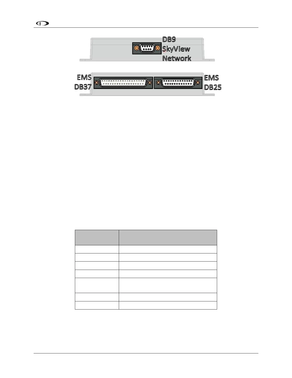
Figure 88–SV-EMS-220 Connectors
The SkyView GPS Receiver module (SV-GPS-250) includes four unterminated wires. These wires
may be trimmed or spliced and extended as needed to suit the installation location. Match the
colors of these wires with the corresponding colors on the display harness as mentioned in the
Serial Connection Section of the SV-GPS-250 Installation and Configuration Chapter.
The SkyView Backup Battery (SV-BAT-320) has one connector. Do not add more wire into the
backup battery wire bundle.
Each SkyView servo has seven unterminated wires. Reference the Autopilot Servo Installation,
Configuration, and Calibration section for more information.
SkyView Equipment Electrical Connector Pin-Out Tables
See tables on the follow pages for connector pin function descriptions. Tables for the USB jacks,
RJ45 jack, OAT connector, and battery connector are not included.
Servo Harness Pin-Out
Power (10 to 30 volts DC)
AP Disengage/Control Wheel Steering
(CWS) Button
Table 54–Servo Wiring