SkyView System Installation Guide - Revision K 11-1
11. SV-XPNDR-26X Installation, Configuration, and Testing
The SV-XPNDR-26X Mode S transponder models are DO-181D compliant Mode S level 2els
datalink transponders, with support for ADS-B extended squitter, which also meets the relevant
environmental requirements of DO-160F/ED-14F. The SV-XPNDR-262 has a nominal power
output of 125 Watts, and meets the power output requirements for Class 2. The SV-XPNDR-261
has a nominal power output of 250 watts, and meets the power output requirements for Class
1. The ADS-B function meets DO-260A class B0. The SV-XPNDR-26X is certified to ETSO 2C112b
and ETSO C166a, and to FAA TSO C112c and C166a.
There are two transponder modules offered by Dynon Avionics. The SV-XPNDR-262 is a Class 2
transponder that is limited to use beneath 15,000 feet and under 175 knots. The SV-XPNDR-261
is a Class 1 transponder that can be used above those limitations. Throughout this manual, they
are often referred to together as the SV-XPNDR-26X for instructions that apply to both versions.
The SV-XPNDR-26X transponder is controlled using SkyView’s on-screen menu system. This
allows the transponder to be mounted separately from the instrument panel and reduces the
amount of panel space taken by the transponder. SkyView also provides pressure altitude
directly to the transponder, eliminating the need for a separate altitude encoder.
The SV-XPNDR-26X transponder runs from either 14 volt nominal or 28 volt nominal DC power
supply with no configuration changes required.
The SV-XPNDR-26X transponder responds to both legacy Mode A/C interrogations and to Mode
S interrogations from both ground radar and airborne collision avoidance systems. In all cases,
the interrogations are received by the transponder on 1030MHz, and replies are transmitted on
1090MHz.
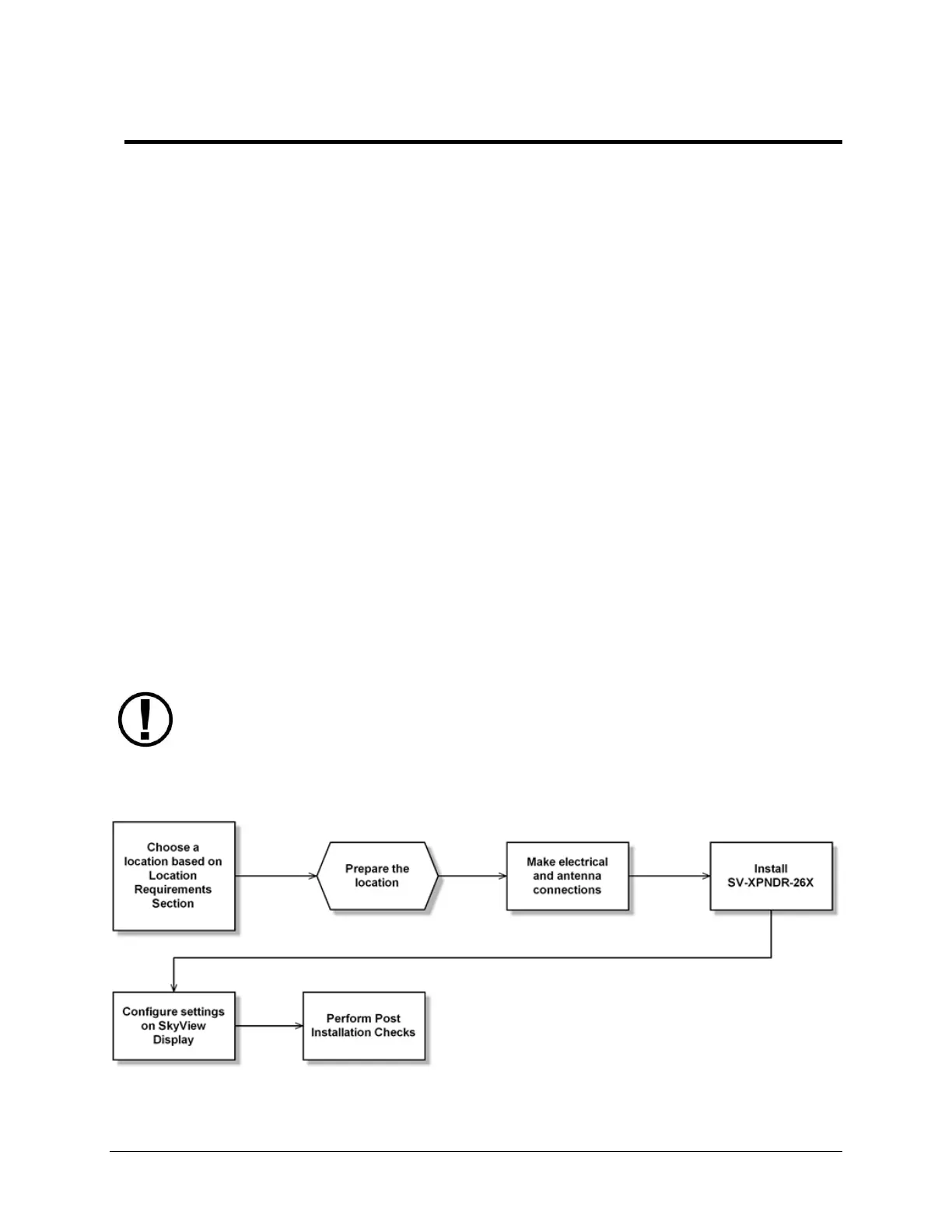
Figure 65 has a high-level overview of a suggested SV-XPNDR-26X installation, configuration,
and testing procedures:
Figure 65 - Suggested SV-XPNDR-26X Installation, Configuration, and Testing Procedure
Read and understand the System Planning Chapter before installing the SV-
XPNDR-26X.