SV-XPNDR-26X Installation, Configuration, and Testing
SkyView System Installation Guide - Revision K 11-11
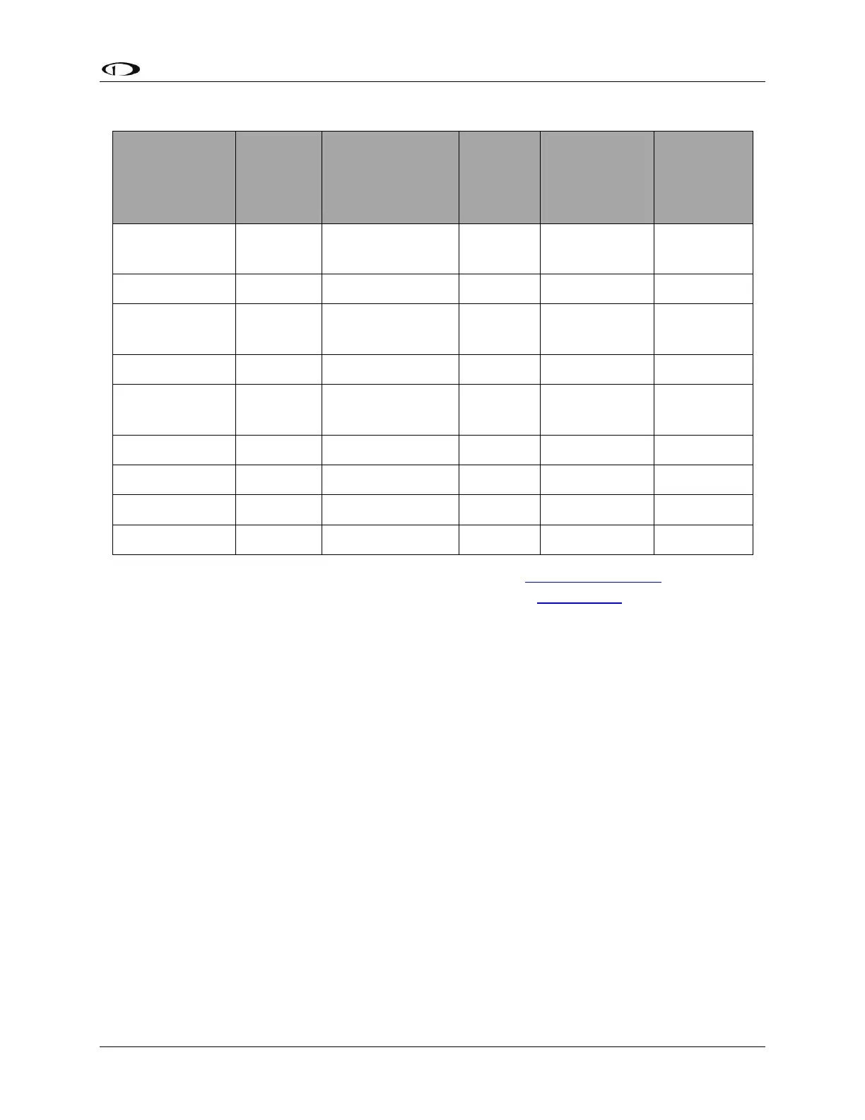
Insertion Loss
dB/meter at
1090MHz
Electronic
Cable
Specialists
Type
Contact Electronic Cable Specialists on +1 414 421 5300 or at www.ecsdirect.com for their data
sheets. Contact SSB-Electronic GmbH on +49-2371-95900 or at www.ssb.de for their data
sheets.
When routing the cable, ensure that you:
Route the cable away from sources of heat.
Route the cable away from potential interference sources such as ignition wiring, 400Hz
generators, fluorescent lighting and electric motors.
Allow a minimum separation of 300 mm (12 inches) from an ADF antenna cable.
Keep the cable run as short as possible.
Avoid routing the cable round tight bends.
Avoid kinking the cable even temporarily during installation.
Secure the cable so that it cannot interfere with other systems.
Antenna TNC Connector
This section describes the technique for attaching the antenna cable to a TNC connector. A TNC
connector is not supplied with the SV-XPNDR-26X. The SV-XPNDR-26X has a female TNC
connection. Therefore, you will need to source a male TNC connector that is compatible with
the antenna cable type that meets your aircraft’s needs.