SV-GPS-250 Installation and Configuration
SkyView System Installation Guide - Revision K 8-3
Harness and SV-GPS-
250 Wire Color
SV-GPS-250 Tx /
Serial Port 5 Rx
SV-GPS-250 RX /
Serial Port 5 Tx
Table 38–SV-GPS-250 Serial Connection Details
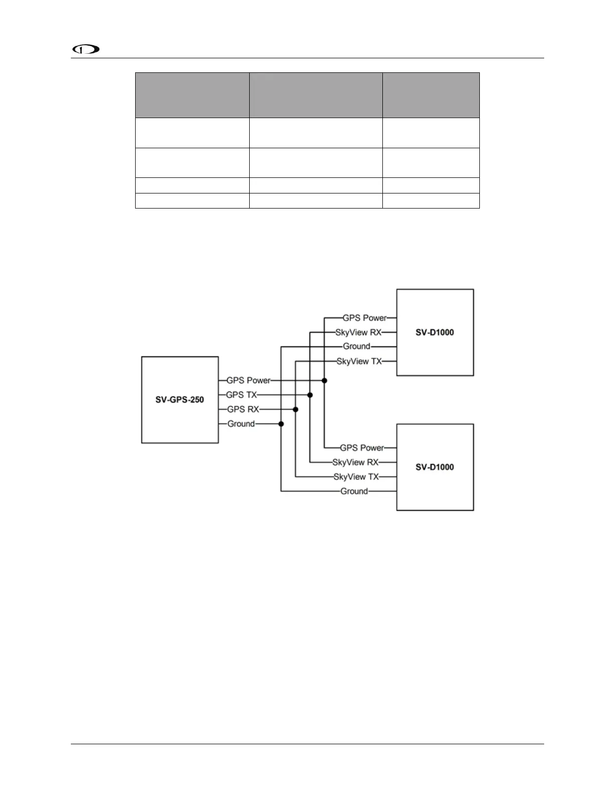
As mentioned before, if there are two or more displays in your SkyView system, all four of the
SV-GPS-250 module’s wires should be connected to all displays in parallel. This wiring scheme is
illustrated in Figure 49.
Figure 49–SV-GPS-250 Connected to Multiple SkyView Displays
If there is more than one SV-GPS-250 in your system, use the same scheme in Figure 49 on
different display serial ports for the other SV-GPS-250 modules, but connect power and ground
for the other SV-GPS-250 modules to the same power and ground connections (black and
orange wires) that are provided in the serial port 5 wiring bundle on the display harnesses.
Configuration
Go to the Serial Port Setup Menu (SETUP MENU > LOCAL DISPLAY SETUP > SERIAL PORT
SETUP>SERIAL PORT 5 SETUP) and then configure serial port 5 as follows:
SERIAL IN DEVICE: Dynon SV-GPS-250
SERIAL IN FUNCTION: POS 1
SERIAL IN/OUT BAUD RATE: 38400