SV-EMS-220 Installation and Configuration
SkyView System Installation Guide - Revision K 7-33
Connect the red wire to SV-EMS-220 D37 pin 18 (red/white). This connection may be shared
with other sensors, depending on your installation.
Connect the green wire to SV-EMS-220 D37 general purpose input of your choosing (nominally
pin 8)
Connect the black wire to Ground. Any the black ground wires on the SV-EMS-220 D37 harness
are suitable for this purpose.
Legacy Dynon-Supplied Fuel Pressure Sensors (100411-000 and 100411-001)
First, mount the fuel pressure sensor to a fixed
location using an Adel clamp or other secure
method such as using a transducer mounting
block on the firewall. The fuel pressure sensor
must not be installed directly to the engine due
to potential vibration problems. Next, connect
the fuel sensor to the engine using appropriate
hoses
and fittings. Its pressure port has a 1/8-27 NPT pipe thread fitting; you may need adapters to
connect to the pressure port on your engine. Locate the correct fuel pressure port for your
engine. This port must have a pressure fitting with a restrictor hole in it. This restrictor hole
ensures that, in the event of a sensor failure, fuel leakage rate is minimized, allowing time for
an emergency landing.
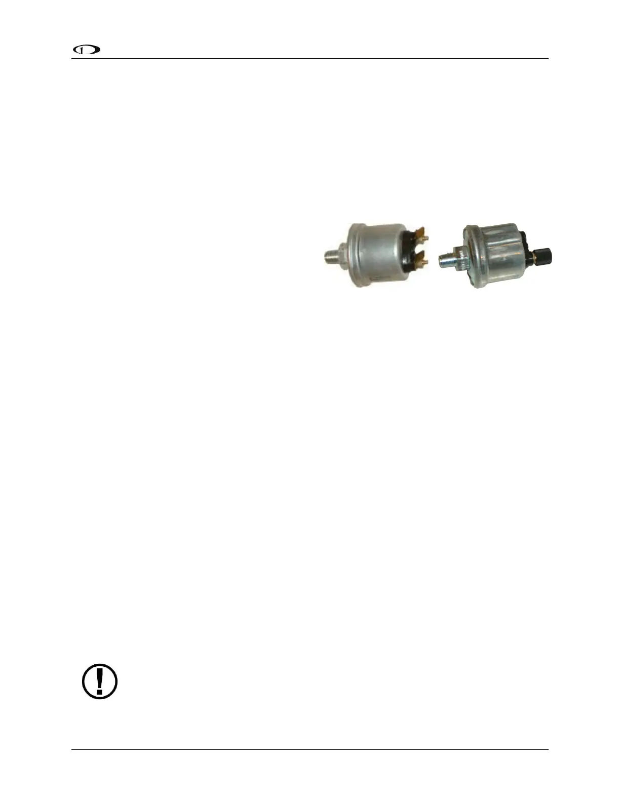
Carbureted engines–Use the 0-30 PSI sensor (Dynon P/N 100411-000). Crimp a standard ¼”
female Faston onto one of the ground wires coming from the EMS 37-pin Main Sensor Harness
or another ground source such as a local engine ground. Crimp another ¼” female Faston onto
a general purpose input pin wire. Push the two Fastons onto the two terminals on the fuel
pressure sensor. Polarity is not important. If you are converting from a GRT EIS system, you
must disconnect the external resistor pull-up from the fuel pressure output. This will make the
sensor output equivalent to the sensor supplied by Dynon Avionics.
Injected engines–Use the 0-80 PSI sensor (Dynon P/N 100411-001). Crimp a standard #8 ring
terminal onto the SV-EMS-220 general purpose input wire of your choice. Unscrew the stud cap
from the threaded stud. Place the ring terminal on the stud and secure the cap down
sandwiching the ring terminal. If the connection between the sensor and your engine is non-
metallic, you must connect the sensor case to ground through other means. The best way to
accomplish this is by sandwiching a ground-connected ring terminal between the sensor and
the mating fitting.
Due to vibration issues, never connect the sensor directly to the engine.
Figure 34–Example Fuel Pressure Sensors