SV-XPNDR-26X Installation, Configuration, and Testing
11-6 SkyView System Installation Guide - Revision K
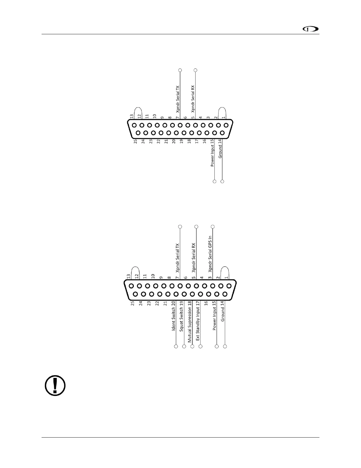
The following figure shows a typical installation, as viewed from the wiring side of the D25
connector:
Figure 69 - Typical SV-XPNDR-26X Connections (Rear Pin Insertion View)
The following figure shows all possible connections, as viewed from the wiring side of the D25
connector:
Figure 70 - All Possible SV-XPNDR-26X Connections (Rear Pin Insertion View)
Note that pins 1 / 2, and pins 12 / 13 must be connected to each other as depicted
above via your wiring harness. They are not shorted internally.