Accessory Installation and Configuration
14-6 SkyView System Installation Guide - Revision K
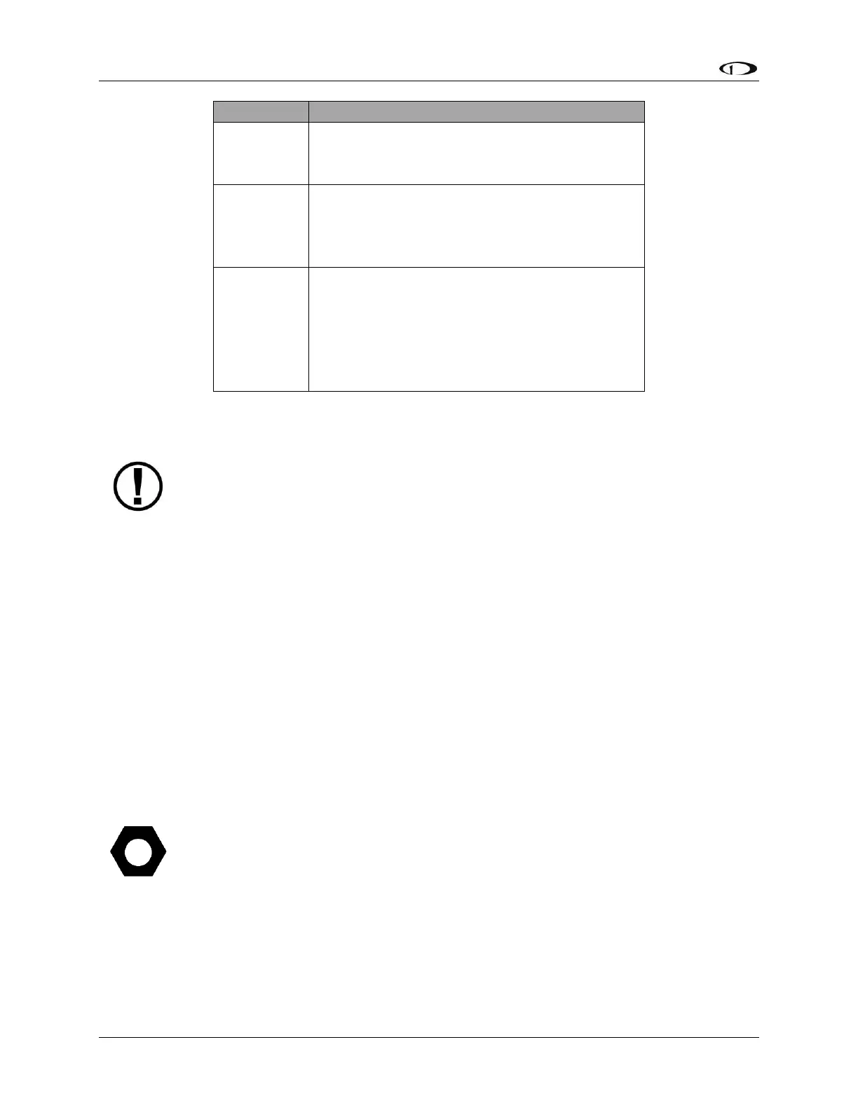
Connected through a pilot-accessible switch to
10 to 15 volt DC supply.
Must handle up to 10 amps.
Must have a constant connection to ground.
This is required for the warning light to
operate when controller is powered off or not
functioning. Line must handle up to 10 amps.
Connected to a light bulb (or resistor & LED)
tied to switched ship’s power. This line is
grounded when the heater controller is
powered off or not functioning. Connection
can handle no more than 1 amp. Current
depends on light source connected.
Table 45–Controller Power Wiring Details
Heater Status Connection
The probe heater functions properly whether or not you make this connection. It is
simply a status output for your convenience.
The white heater status wire is grounded when the probe heater is turned off or not
functioning properly. This wire should be connected to a light on the panel, whose other
terminal is connected to switched aircraft power. When the heater is on and functioning
properly, the white heater status line is open, leaving the indicator light turned off. When there
is no power to the heater controller–or it is not functioning properly–the white line is
grounded, turning the indicator light on. This parallels annunciator behavior in FAA certificated
aircraft.
Aircraft Spruce P/N 17-410 is an example of a light that will work for this application. An LED
and resistor in series will also suffice. If you use an LED as the indicator, you must choose a
resistor that delivers the appropriate current to the LED, and can accommodate the power
required for its current and voltage drop. Also note that the power and ground connections on
LEDs are not reversible.
If there is an SV-EMS-220 in the same SkyView system, consider using one of its
general purpose inputs configured as a contact for heated pitot operational status.
Connect the heater status output directly to the EMS module’s pin. There is no
need for additional resistors or lights. Reference the EMS Sensor Definitions,
Mapping, and Settings Section for general purpose input configuration details.