System Planning
SkyView System Installation Guide - Revision K 2-13
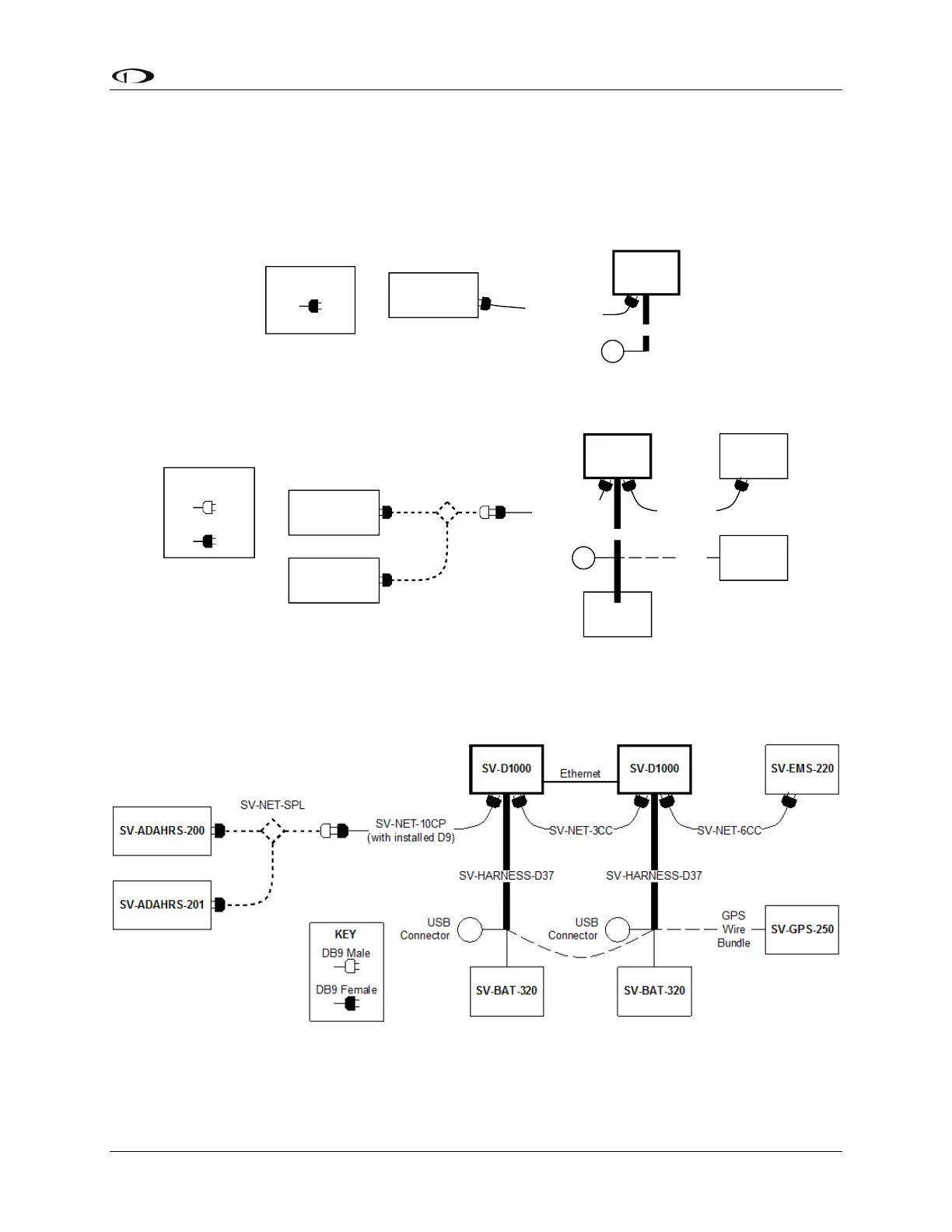
following diagrams illustrate several example SkyView systems and the components needed to
build them. Diagrams do not show a connection to aircraft power and do not imply an
installation location. Additionally, cable lengths and models pictured below should not be
blindly used as a “prescription”. Always consider your aircraft’s particular geometry and module
installation locations before purchasing harnesses, hubs, and splitters.
SV-D1000
USB
Connector
SV-HARNESS-D37
SV-ADAHRS-200
SV-NET-10CP
(with installed D9)
KEY
DB9 Female
Figure 4–SkyView System with One Display and One ADAHRS
SV-D1000
USB
Connector
SV-BAT-320
SV-HARNESS-D37
SV-EMS-220
SV-NET-6CC
SV-ADAHRS-200
SV-ADAHRS-201
SV-NET-SPL
SV-GPS-250
GPS
Wire
Bundle
SV-NET-10CP
(with installed D9)
KEY
DB9 Male
DB9 Female
Figure 5–SkyView System with One Display, One EMS, One GPS, One Backup Battery, and Two Redundant
ADAHRS
Figure 6–SkyView System with Two Redundant Displays, One EMS, Two Backup Batteries (One per Display), One
GPS, and Two Redundant ADAHRS