Parameter List and Menu Structure of VS 300
134
Doku-Version 2.05 - Firmware 2.10 - 15. September 2017
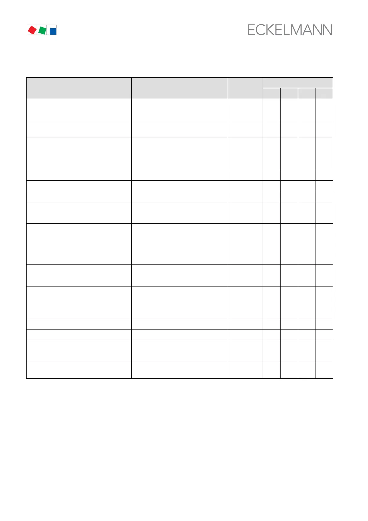
S Menu 3-4 Monitoring CL1/CL2
Monitoring POS: XXXXX Entry
Default
NT LT HP Dim.
tx-Hi Warn. CL1 XXX °C High Pressure CL1 alarm is generated if
temperature in CL1 rises above this level
1)
-30 - 55 0 -20 52 °C
tx-Hi Res. CL1 XXX °C Reset High Pressure CL1 alarm when
temperature drops below this level
1)
-35 - 48 -5 -2 45 °C
tx-Lo CL1 XXX °C Low Pressure CL1 alarm is generated if
temperature in CL1 rises above this level;
when activated, compressors of CL1 are
disabled at temperature below this level
-> only with LP control
-50 - 20 -25 -46 10 °C
Del.to-Hi CL1 XXX m High Pressure CL1 alarm delay
1)
0 - 60 10 10 10 min
Del.to-Lo CL1 XXX m Low Pressure CL1 alarm delay 0 - 60 10 10 10 min
Min Diff.toCL1 XXX K Minimum allowed difference to - tc
2)
5..15 --- --- - K
Starts/h CL1 XX Max. number of hourly compressor/fan
stage starts in CL1;
only with actuating mode by run time.
4 - 60 10 10 60 1/h
tx-Hi Warn. CL2 XXX °C High Pressure CL2 alarm is generated if
temperature in CL2 rises above this level;
when activated, compressors in CL1 can
be disabled - only with combination of LP
controller in CL1 and HP controller in
CL2.
-30 - 55 0 -20 52 °C
tx-Hi Res. CL2 XXX °C Reset High Pressure CL2 alarm when
temperature drops below this level;
reset compressor disabling CL1
-35 - 48 -5 -2 45 °C
tx-Lo CL2 XXX °C Low Pressure CL2 alarm is generated if
temperature in CL2 rises above this level;
when activated, compressors of CL2 are
disabled at temperature below this level
-> only with LP control.
-50 - 20 -25 -46 10 °C
Del.to-Hi CL2 XXX m High Pressure CL2 alarm delay
1)
0 - 60 10 10 10 min
Del.to-Lo CL2 XXX m Low Pressure CL2 alarm delay 0 - 60 10 10 10 min
Starts/h CL2 XX Max. number of hourly compressor/fan
stage starts in CL2;
only with actuating mode by run time.
4 - 60 10 10 60 1/h
Stg.tmax HP2. XX m No. of compressors running3) in CL at HP
fault in CL2.
0..
3)
- -
3)
-
1)
Only shown when control loop is configured as HP controller.
2)
Only show when Control Loop 1 is configured as LP controller and Control Loop 2 as HP controller.
3)
After changing compressor stages in CL1, this value is reset to the new default according to the table be-
low. Only shown when CL1 is configured as LP controller (NT or LT) and RK2 as HP controller: