Parameter List and Menu Structure of VS 300
135
Doku-Version 2.05 - Firmware 2.10 - 15. September 2017
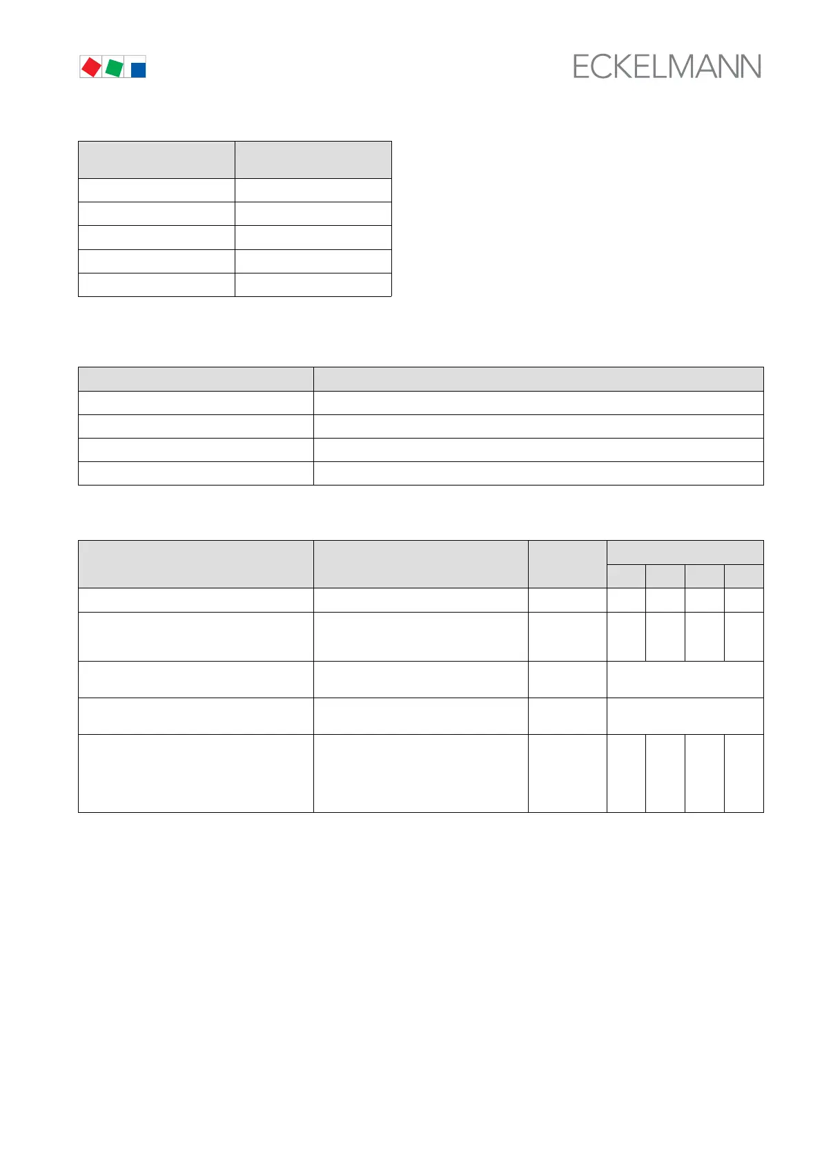
No. of compressor stages Default No. of compressor
stages at HP fault
1 - 2 1
3 - 5 2
6 - 7 3
8 - 10 4
11 - 12 5
S Menu 3-5 Inputs
INPUTS POS: XXXXX
1 INPUT 1 Next: Screen 3-5-1
2 INPUT 2 Next: Screen 3-5-2
3 INPUT 3 Next: Screen 3-5-3
4 INPUT 4 Next: Screen 3-5-4
S Menu 3-5-1 INPUT 1
INPUT 1 POS: XXXXX Entry
Default
NT LT HP Dim.
Time delay XX s External alarm delay in seconds 0 - 60 0 0 0 s
Alarm message:
XXXXXXXXXXXXXXXXXXXXXXXXX
Text displayed on occurrence of external
alarm (through digital input 1): Default
Ext. Alarm I1
Text - - - -
Function: ExtAlarm → Function performed when digital input 1 is
activated
Screen 3-5-1-a
linked to: → Enter control loop to receive function in
itiated through digital input 1
Screen 3-5-1-b
Polarity X Polarity of digital input 1
0: Low active (activated at signal voltage
0/cable break)
1: High active (activated at signal voltage
= 230 V AC)
0 - 1 0 0 0 -