MANUAL ELDES ESIM264 V2.0 13
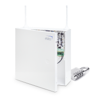
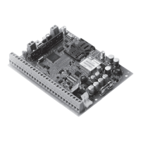
ESIM264
BELL- BELL+
RED +
BLACK -
ESIM264
BELL- BELL+
GND
+12V
BELL
AUX-
Type 1 Type 2 Type 3 Type 4 Type 5
Normally open contact
with 5,6KΩ end of line
resistor
Normally closed con-
tact with 5,6KΩ end of
line resistor
Tamper and 5,6KΩ
end of line resistor
and 3,3KΩ end of line
resistor with normally
closed contact
ATZ Mode: 5,6KΩ end
of line resistor and nor-
mally closed contact
with 3,3KΩ end of line
resistor and normally
closed contact
ATZ Mode: Tamper,
5,6KΩ end of line
resistor, 5,6KΩ end of
line resistor with nor-
mally closed contact
and 3,3KΩ end of line
resistor with normally
closed contact.
COM
BELL-
BELL+
G
Y
C2
AUX-
AUX+
AC/DC
AC/DC
Z1
COM
Z2
Z3
COM
Z4
DATA
+5V
MIC-
MIC+
BUZ-
C1
BUZ+
COM
COM
Z6
Z5
MIC
BUZ
SIREN
iButton®
key reader
Temperature sensor
EKB2EKB3
EPGM1
5.6k
Z1
Z2
Backup Battery
12V 1.3-7Ah
Metal box
PE contact
Relay
module
500 mA max.
Z4
Z3
Z5
Z6
5.6k
5.6k
5.6k
5.6k
Fuse 500 mA
~230V 50Hz
~16-24V
AKU+
AKU-
Fig. No. 3
Fig. No. 4
Fig. No. 2
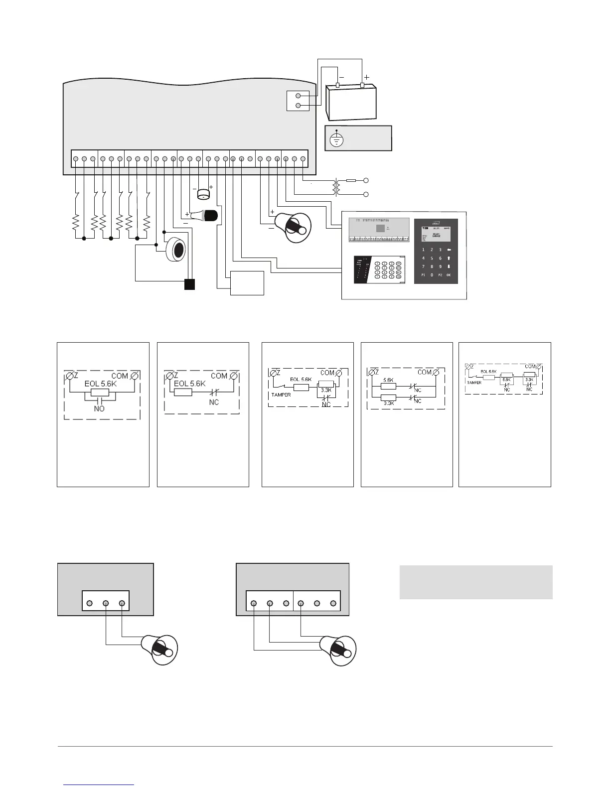
2.3 Wiring Diagrams
2.3.1 General Wiring
2.3.2 Zone Connection Types
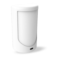
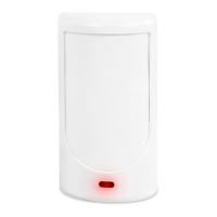
2.3.3 Siren
2-wired siren
1. Connect positive siren wire (red)
to BELL+ contact.
2. Connect negative siren wire
(black) to BELL- contact.
Self-contained siren
1. Connect negative GND siren wire to AUX- contact.
2. Controlling BELL siren wire must be connected to BELL- contact.
3. Connect positive +12V siren wire to BELL+ contact.
NOTE: BELL- is the commuted
contact intended for siren control.