MANUAL ELDES ESIM264 V2.0 75
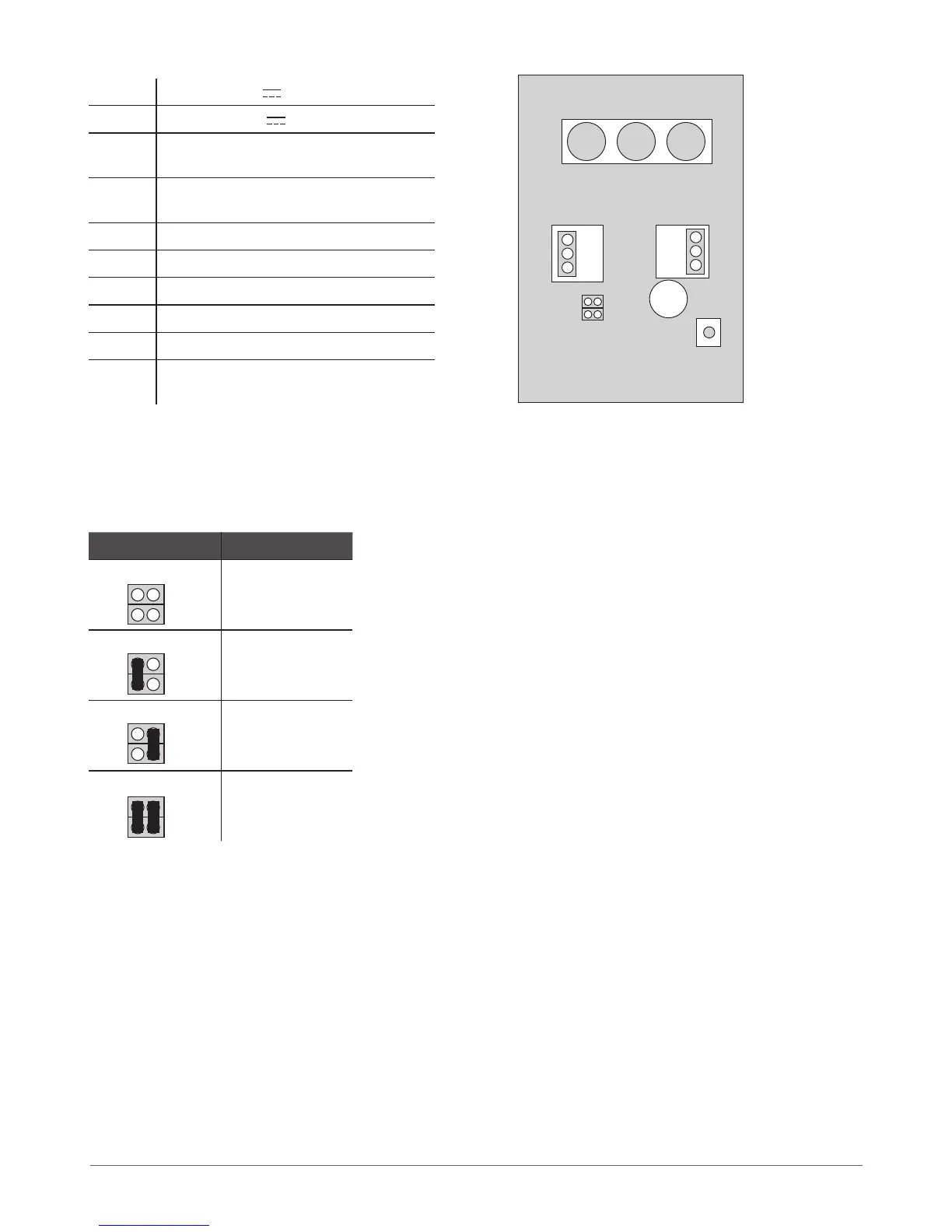
7.1.1.3 Connector and Main Unit Functionality
Vin Positive 12-14V power supply contact
COM Negative 12-14V power supply contact
G RS485 interface for commu-
nication (green wire)
Y RS485 interface for commu-
nication (yellow wire)
COM Common connector for Z1
Z1 Security zone connector
A0 Keyboard address pin
A1 Keyboard address pin
Buzzer Mini buzzer providing sound signals
Tamper Tamper-button for EKB2 enclo-
sure status monitoring
7.1.1.4 Keyboard Address
A0 and A1 pins located on the back side of the keyboard are intended to set keyboard address. The keyboard address is set by putting
the jumper (-s) on the pins. ESIM264 system allows to connect up to 4 EKB2 keyboards - each set under dierent address. Jumper
combinations for dierent keyboard address conguration are indicated in the table below.
Jumper position Address
Keyboard 1
Keyboard 2
Keyboard 3
Keyboard 4
The address of each connected keyboard is also indicated in ELDES Conguration Tool software.
Buzzer
VIN
COM
Z1
A0 A1
G
Y
COM
Tamper
A0
A0
A0
A0
A1
A1
A1
A1
Fig. No. 11