76
7.1.2 Installation
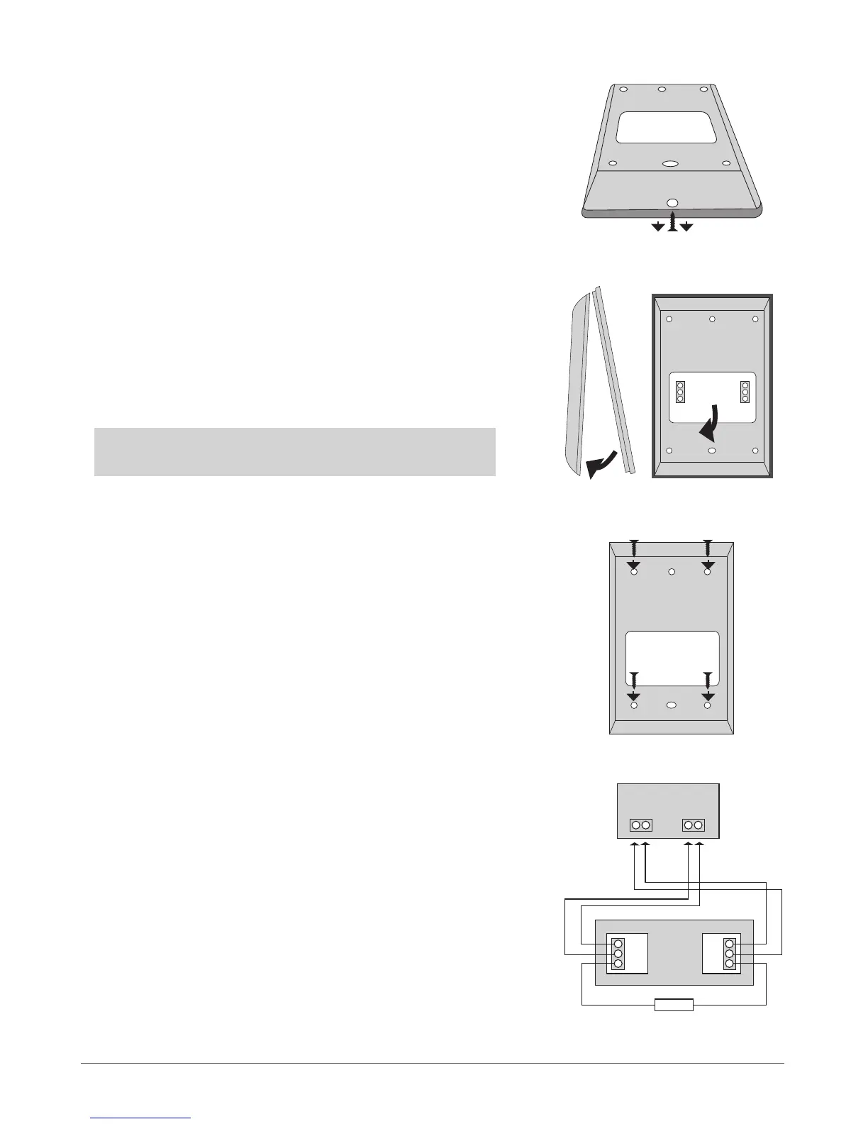
1. Remove the screw located on the bottom side of the enclosure (see Fig.
No. 12)
2. Detach keyboard holder from EKB2 keyboard by gently pulling the
holder towards yourself (see Fig. No. 13).
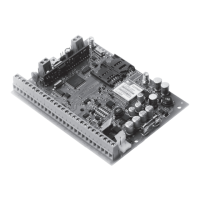
3. Fix the keyboard holder on the wall using the screws. (see Fig. No. 14)
4. Disconnect ESIM264 main power supply and backup battery.
5. Wire up keyboard contacts to ESIM264 alarm system respectively – Vin
to AUX+, COM to AUX-, Y to Y, G to G.
6. Z1 and COM contacts must be connected with resistor of 5,6kΩ nominal
(see Fig. No. 12). As keyboard zone Z1 is disabled by default, it can be en-
abled by SMS, EKB2 keyboard, EKB3 keyboard and ELDES Conguration
Tool. Keyboard zone Z1 must be enabled and resistor connected even if
the tamper button alone is required.
7. Set the keyboard address by putting the jumper on A0 and A1 pins (see
chapter 7.1.1.4 Keyboard Address).
8. Fix the keyboard into the holder.
ATTENTION! Before xing the keyboard into the holder, please, make
sure that the tamper button is properly pressed (see Fig. No. 11).
9. Screw up the bottom side of the enclosure. (see Fig. No. 12)
10. Power up ESIM264 alarm system.
11. EKB2 keyboard is ready.
Fig. No. 14
Fig. No. 15
Fig. No. 12
Fig. No. 13
VIN
Y
G
AUX- AUX+
EKB2
COM
Z1
G
Y
COM
5,6kΩ
ESIM264