88
7.2.2 Installation
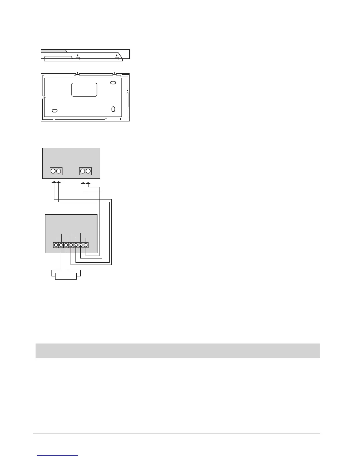
1. Detach keyboard holder from EKB3 keyboard . Keyboard holder detach points are marked with arrows (see Fig. No. 18).
2. Disconnect alarm system ESIM264 power supply and backup battery before connecting the wires.
3. Wire up keyboard contacts to ESIM264 alarm system respectively – AUX+ to AUX+, AUX- to AUX-, Y to Y, G to G. (see Fig. No. 19).
4. Z1 and COM contacts must be connected with resistor of 5,6kΩ nominal (see Fig. No. 19). As keyboard zone Z1 is disabled by de-
fault, it can be enabled by SMS, ELDES Conguration Tool, EKB2 and EKB3 keyboard. Z2 contact is permanently inactive. Keyboard
zone Z1 must be enabled and resistor connected even if the tamper button alone is required.
5. Set the keyboard address by combining DIP switch positions (see 7.2.1.5 Keyboard Address).
6. Inx the keyboard into the holder (see Fig. No. 18).
ATTENTION! Before xing the keyboard into the holder, please, make sure that the tamper is properly pressed (see Fig. No. 17).
7. Power up ESIM264 alarm system.
8. EKB3 keyboard is ready.
BACK SIDE
DOWN SIDE
Fig. No. 18
Fig. No. 19
Z2 Z1
COM Y
G
AUX-
AUX+
EKB3
ESIM264
Y
G
AUX- AUX+
5,6kΩ