14
2.3.4 iButton® Key Reader & Mini Buzzer
Supported iButton® Key Model: Maxim®/Dallas® DS1990A
The iButton® key reader can be installed with mini buzzer or separately. The mini buzzer is
intended for audio indication of Entry/Exit Delay countdown providing short beeps.
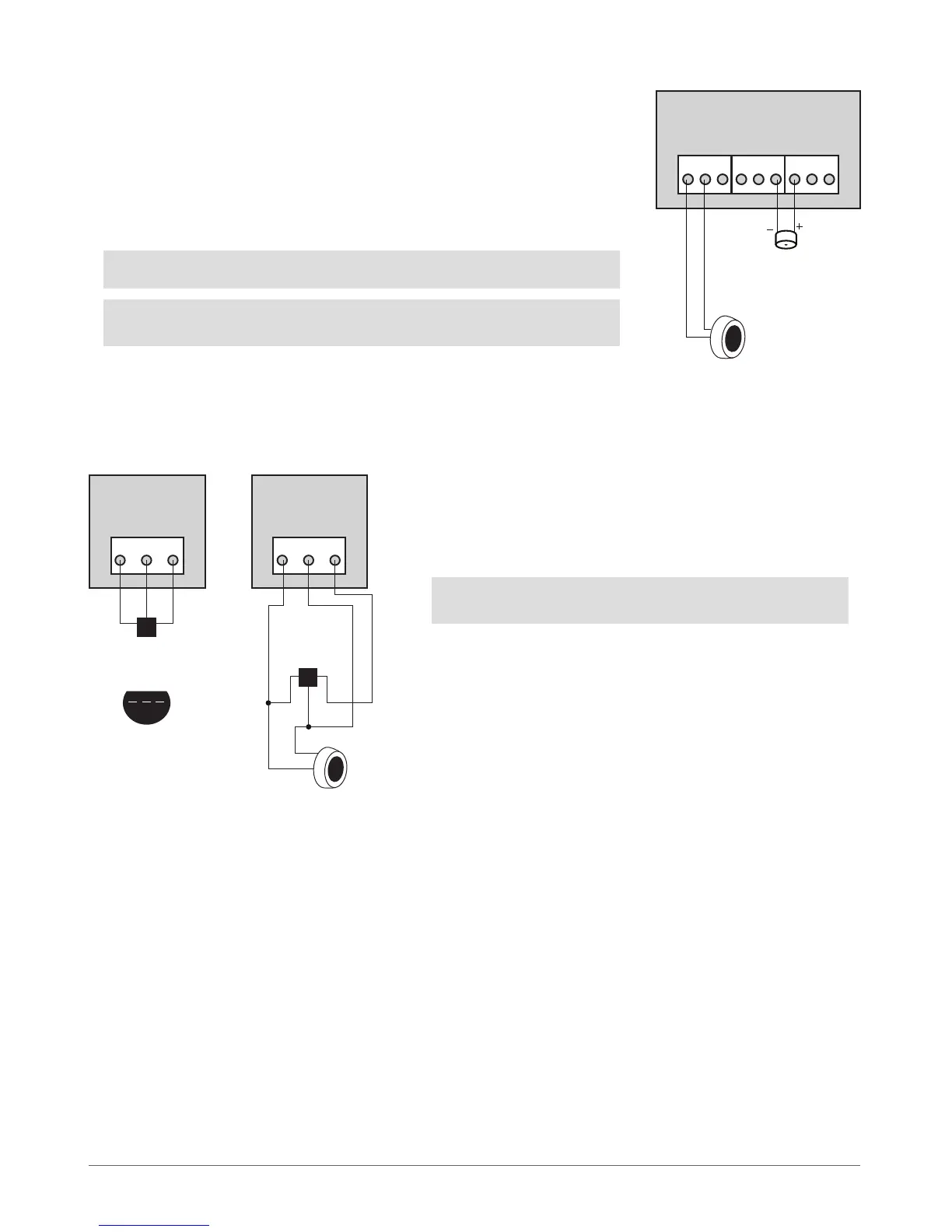
1. Connect iButton® key reader contact wires to 1-Wire® interface: COM and DATA
contacts respecti vely.
2. Connect mini buzzer negative contact wire to BUZ- and positive contact wire to
BUZ+.
3. Additionally, a LED indicator for visual indication can be installed in parallel to mini
buzzer or instead. Connect LED anode contact to BUZ- and cathode to BUZ+.
NOTE: The installation of mini buzzer is not necessary if EKB/EKB3 keyboard is used.
ATTENTION: The wire length for connection to 1-Wire® interface can be up to 30
meters max.
ESIM264
MINI BUZZER
iButton®
key reader
DS1990A
BUZ+BUZ-COM DATA
Fig. No. 5
Fig. No. 6
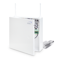
2.3.5 Temperature Sensor & iButton® Key Reader
Supported iButton® Key Model: Maxim®/Dallas® DS1990A
Supported Temperature Sensor Model: Maxim®/Dallas® DS18S20, DS18B20
ESIM264
+5VDATACOM
TEMPERATURE SENSOR
TEMPERATURE SENSOR
1
1
2
2
3
3
BOTTOM VIEW
GND DATA +5V
DS18S20, DS18B20DS18S20, DS18B20
1 2 3
ESIM264
+5VDATACOM
iButton®
key reader
DS1990A
1. Connect temperature sensor 1, 2, 3 contacts to 1-Wire® interfa-
ce: COM, DATA and +5V contacts respectively.
2. When connecting iButton® key reader in parallel to tempera-
ture sensor, connect iButton® key reader contact wires to COM
and DATA contacts respectively.
ATTENTION: The wire length for connection to 1-Wire® interface
can be up to 30 meters max.