EPSON Stylus Pro 4400/4450/4800/4880/4880C Revision C
Disassembly & Assembly Disassembly Procedures 226
4.2.4 Circuit Board Removal
This section describes steps for removing “C593 MAIN Board“, “Power Supply
Board”, and each “C593_SUB Board“.
4.2.4.1 C593 MAIN Board
1. Remove "Holder, Roller, Unit" (p214).
2. Remove "Paper Guide Assy., M, SP" (p215).
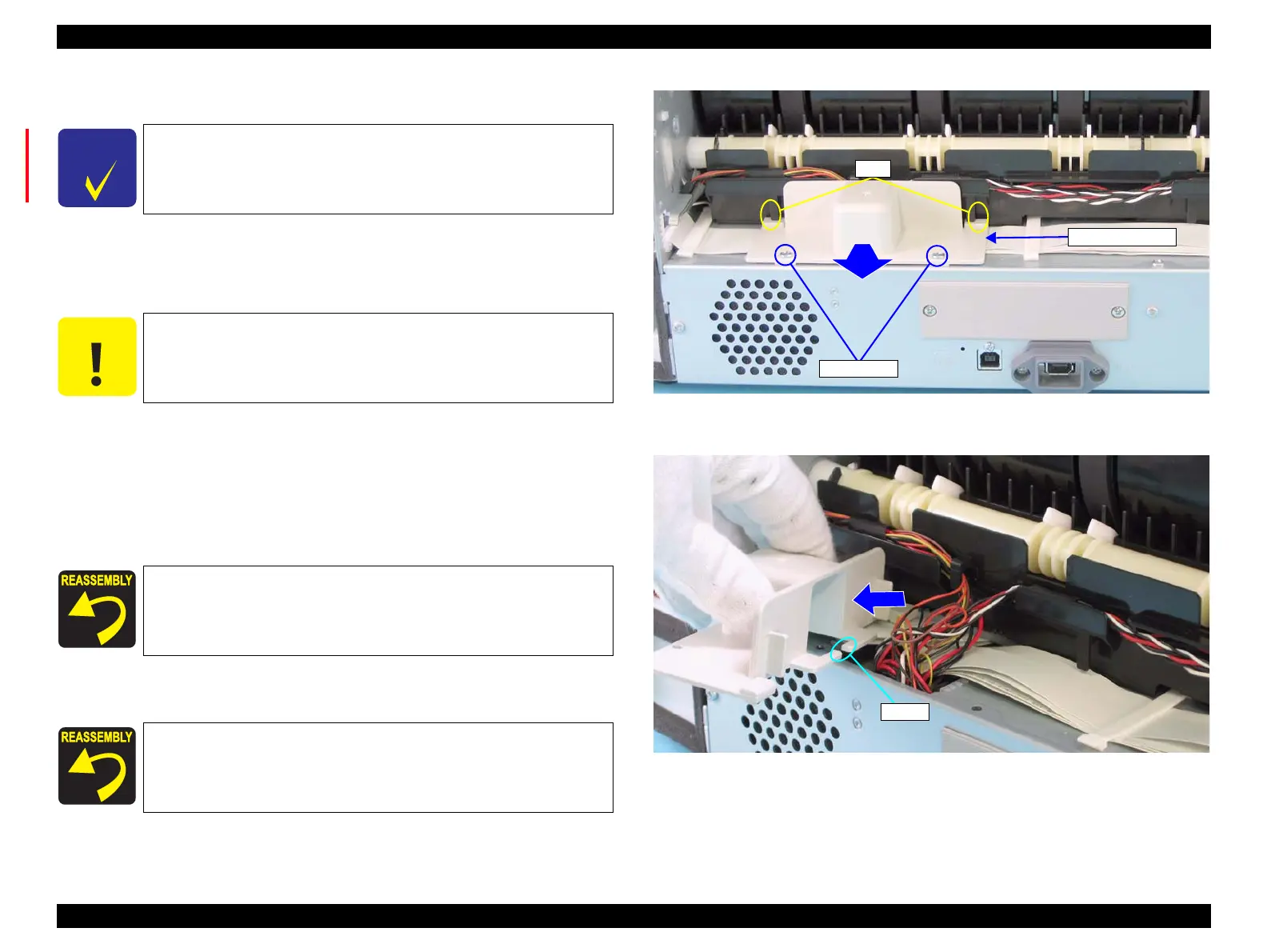
3. Remove the two screws securing "Cover, Harness". (Refer to Figure 4-30.)
C.B.S. 3x8: 2 pcs.
4. Slide "Cover, Harness" outward. (Refer to Figure 4-30.)
5. Release all harnesses through the "Cover, Harness" notch and remove the
"Cover, Harness". (Refer to Figure 4-31.)
Figure 4-30. Screws Securing the Cover, Harness
Figure 4-31. Cover, Harness Removal
C H E C K
P O I N T
The board used for Stylus 4400/4800 is "C593 MAIN Board",
and "CA00 MAIN Board" is used for Stylus Pro 4450/4880/
4880C. The explanation in this section is based on Stylus
Pro 4400/4800.
C A U T I O N
Be sure to insert and unplug FFCs vertically. (Inserting/
Unplugging at an angle can damage shorten or disrupt the
terminals inside the connector and cause damage to circuit
board components.)
Insert "Cover, Harness" into the two ribs of "Paper Guide,
Lower".
Do not allow any harness to jut out from under the "Cover,
Harness".
Ribs
C.B.S. 3x8
Cover, Harness
Notch

 Loading...


