4. Commissioning positioning systems
4−31
Festo P.BE−SPC200−WIN−PISA−CD−EN en 0901d
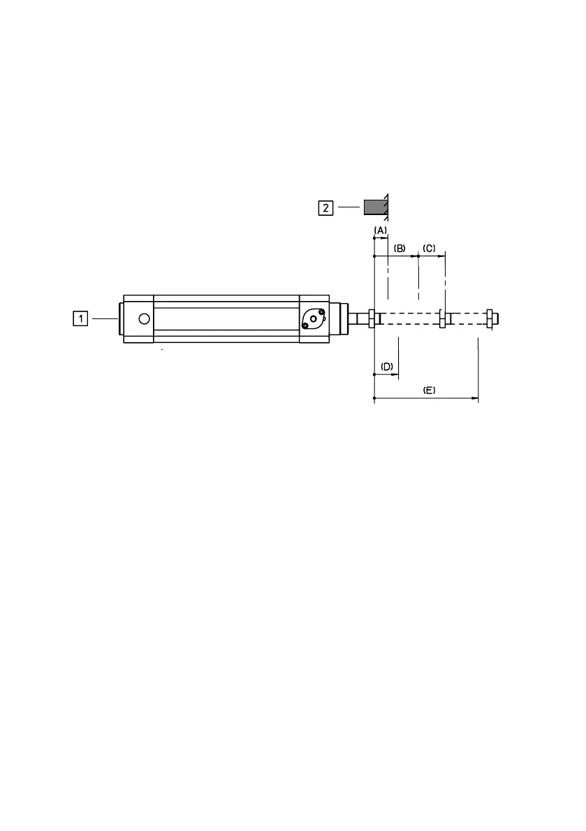
Fig.4/13 shows an example for piston−rod drives with
incremental measuring system.
1 Piston−rod drive here DNCI with integrated,
incremental measuring system
2 Reference stop either the end stop of the
drive itself (reproducibility:
~ 1/10 mm) or fitted externally
(reproducibility: ~1/100mm)
Reference points:
(A) Reference position
(B) Project zero point
(C) Actual position
(D) Lower software end position
(E) Upper software end position
Fig.4/13: Reference points (piston−rod drives with incremental measuring system)
Reference position Only with pneumatic drives with incremental measuring
system (e.g.
type DNCI...):
Offset of the reference position, specifies the offset of the axis
zero point from the reference point. It is always a positive
variable. This offset value also influences the controller op
timization of the SPC200, even small values (a few mm) must
be specified as accurately as possible.
Permitted: 0.00 ...
9999.99 [mm] or [°]
 Loading...