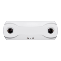
Brickstream® 3D Gen 2 Version 6.2
6/25/2021
©2016-2021 FLIR Integrated
Imaging Solutions Inc.
All rights reserved.
Brickstream® 3D Gen 2 Installation Guide
June 2021
30
Creating the Solution Design
After the initial planning work is complete, the site survey is used to create a complete solution design
that specifies each sensor required and its exact placement within the floor plan, as well as all materials
necessary to implement the solution. This information described in the following sections is given to
the installation team.
After the Site Survey
The site survey provides input for the system design for the site. The output of system design is a bill of
materials (BOM) and an installation document showing sensor locations.
Design Document Line Items
Bill of Materials
Number of sensors
Sensor model number(s), as determined by mounting
height
Sensor power and networking
Mount type and number of mounts
Additional infrastructure, such as cabinets, cables, etc.
Installation document, such as a Site
Installation Specification, typically showing
sensor locations on a top-down floor plan
Use: Visio / AutoCAD / other
Floor plan and coverage must be scaled
Show measurements from at least two fixed objects
(walls, doors) to identify the precise location on the
ceiling where the sensor should be installed
Specify ceiling heights
Determining How Many Sensors You Need
To Determine... You Need to Know...
The number of and type of
sensors needed
The height of the ceiling at the door/coverage area
The width of the door/coverage area
The current (or planned) location(s) and heights of ceiling fixtures in the
area(s) where the sensor(s) will be installed
How to connect to and get
data from the sensors
How the sensors will be networked
Where the network connection/POE source will be located (for cabling)
A general idea of the cabling scope
You can gather this information from the following sources:
n Created and provided by someone else:
n Floor Plans – General Layout
n Reflective Ceiling Plans (RCP’s)

 Loading...