Brickstream® 3D Gen 2 Version 6.2
6/25/2021
©2016-2021 FLIR Integrated
Imaging Solutions Inc.
All rights reserved.
Brickstream® 3D Gen 2 Installation Guide
June 2021
87
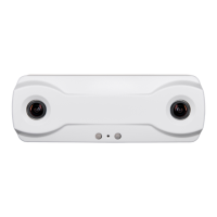
Installing the 3D Gen 2 Sensor On-Site
The proper installation and use of the 3D Gen 2 sensor requires accessories that provide:
n A way to mount the sensor
n Network connectivity
n A power source, such as:
n A Power-over-Ethernet (PoE) switch
n A PoE injector
The following section provides an overview of the different PoE devices and mounts that are available
for use with the 3D Gen 2 sensor.
Powering the 3D Gen 2 Sensor
Industry standard 802.3af PoE connections (with CAT5e Ethernet cable) are supported to facilitate the
combined power and network connection to the 3D Gen 2 sensor.
Note: The 3D Gen 2 sensor is PoE Class 2, so the PoE must
support Class 2 or higher.
Brickstream 3DGen 2 sensors equipped with a USB Wi- Fi BLE dongle that are using Wi- Fi for
connectivity still need to be powered with a PoE device.
Cabling Guidelines
Note: All connections use standard CAT5e or higher Ethernet
cables. No special cables are necessary.
We recommend you follow these industry standard guidelines to ensure that cabling meets sensor and
network requirements:
n Cable should be installed per the Customer’s corporate standards, using plenums, conduits, and
other approved pathways to be used as needed.
n Home-run cables (terminating at the head end) must include a 3m (~10ft) service loop on the
sensor end to provide flexibility in relocating the biscuit mount if needed in future for any reason.
n We recommend using patch panels at the head-end and optional biscuit mounts at the sensor
end of the home-run cables.
n Installer-provided patch cables 1m to 2m (3–6ft) long should connect patch panels to POE
switches.