Figure 73
133198
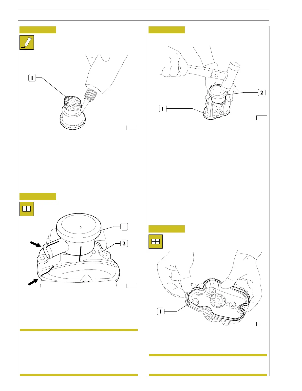
- Apply a regular layer of LO CTITE 510 all aroun d the
blow-by body (1).
Figure 74
133199
- Fit the blow-by (1) on the rocker cover (2) having care
to position the exit hole (1) in the c orrect direction.
Figure 75
133200
- Lean the complete cover assembly on a stiff surface.
- By means of a plastic hammer make su re that the
blow-by (2) goes co mpletely inside its seat on th e rocker
cover (1).
Figure 76
134376
- Position a new gasket (1) in its seat on the rocker cover.
The position of the gasket in t he seat is univocal.NOTE
The position of the blow-by exit hole c an vary
according to the specific applications of the engine.
A wrong positioning of the blow-by body (1) on
the cover (2) may, therefore, result in difficu lt while
refitting the engine aboard specific applications.
NOTE
28
SECTION 3 - INDUSTRIAL APPLICATION
F32 SERIES
Base - April 2009 Prin t P2D 32F005 E