Franke Kaffeemaschinen AG
TD-100441.doc 6 / 7
7 Optional: Connection of the CCI cable to the Inkasso3 PCB
You must first ensure that the cable glands at Positions 5 in Figure 7 are sufficiently large enough
for the three cables.
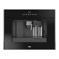
Fig. 9: In addition to Point 6, connect the CCI-RS232 cable and the CCI
power cable, as shown in Figure 8.
The polarity must be taken into account for the CCI power cable; in this case, connect
the brown cable to the flat plug 6.3 mm (GND) – sign. The white cable to the
flat plug 4.8 mm (24 VDC).
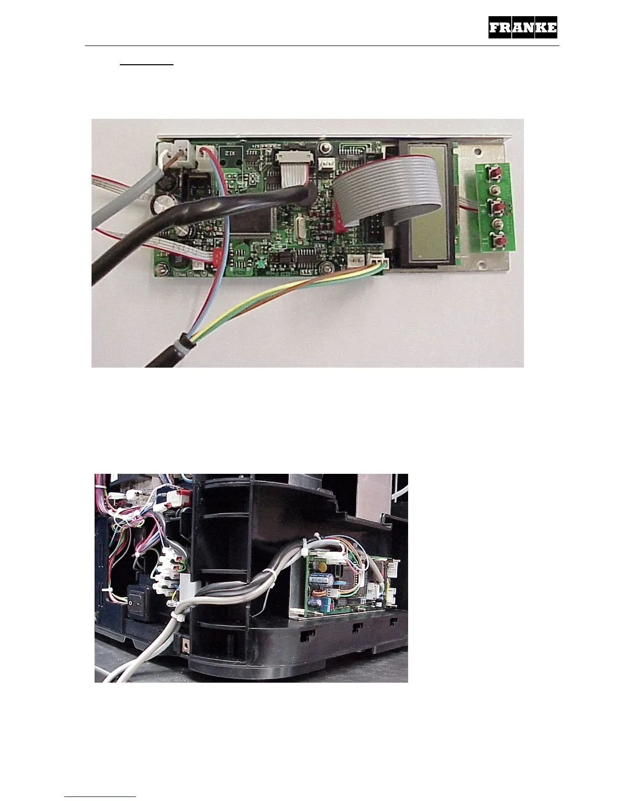
Fig. 10: Overall view. The two additional cables can be clearly seen that are
fed out through the unit.

 Loading...