112
If an increased welding circuit resistance is detected, e.g. after changing the welding torch,
this may mean that the following components are faulty:
- Torch hosepack
- Welding torch
- Grounding (earthing) connection to the workpiece
- Grounding cable
Welding circuit inductivity L [μH]
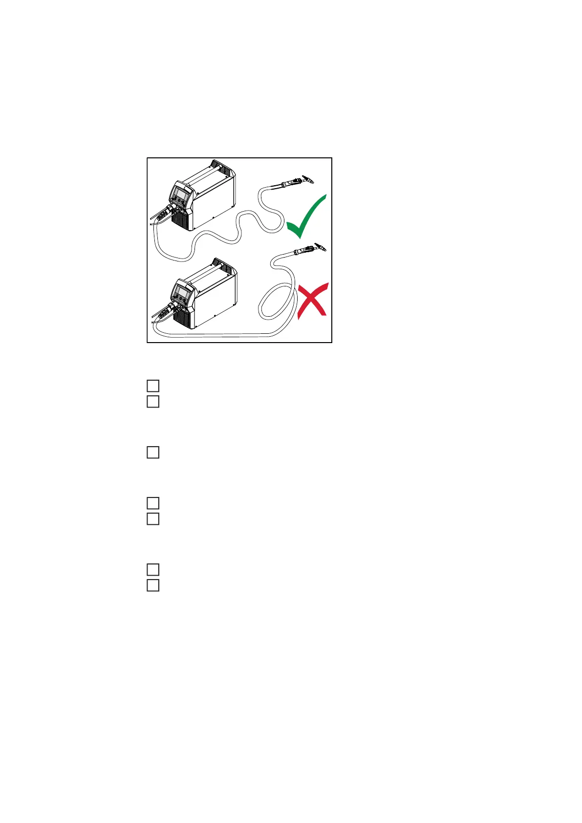
The way that the hosepack is arranged has
a very significant effect on the weld proper-
ties.
Particularly with pulsed-arc welding and AC
welding, a high welding circuit inductivity
may occur, depending on the length of the
hosepack and on the way that it is arran-
ged. The result is that the current rise is re-
stricted.
The weld results can be optimised by chan-
ging the arrangement of the torch hose-
pack.
The hosepack must be laid out as shown in
the illustration.
Performing R/L alignment
Defaults / System / Perform R/L alignment
Press the adjusting dial
The current values are displayed
Select More (turn adjusting dial and press)
The second R/L alignment screen is displayed.
Follow the instructions displayed on the screen
Select More (turn adjusting dial and press)
The third R/L alignment screen is displayed.
Follow the instructions displayed on the screen
Select "More" (turn and press adjusting dial)
The current values are calculated.
After R/L alignment has been completed, a confirmation and the current values are
displayed.
1
2
3
4
5
6
7